Tray Loading System for Injection Molded Parts
Two Tray Stack Positions Dual Conveyor Infeed
Feed moulded parts to the pickup position, then place them into trays.
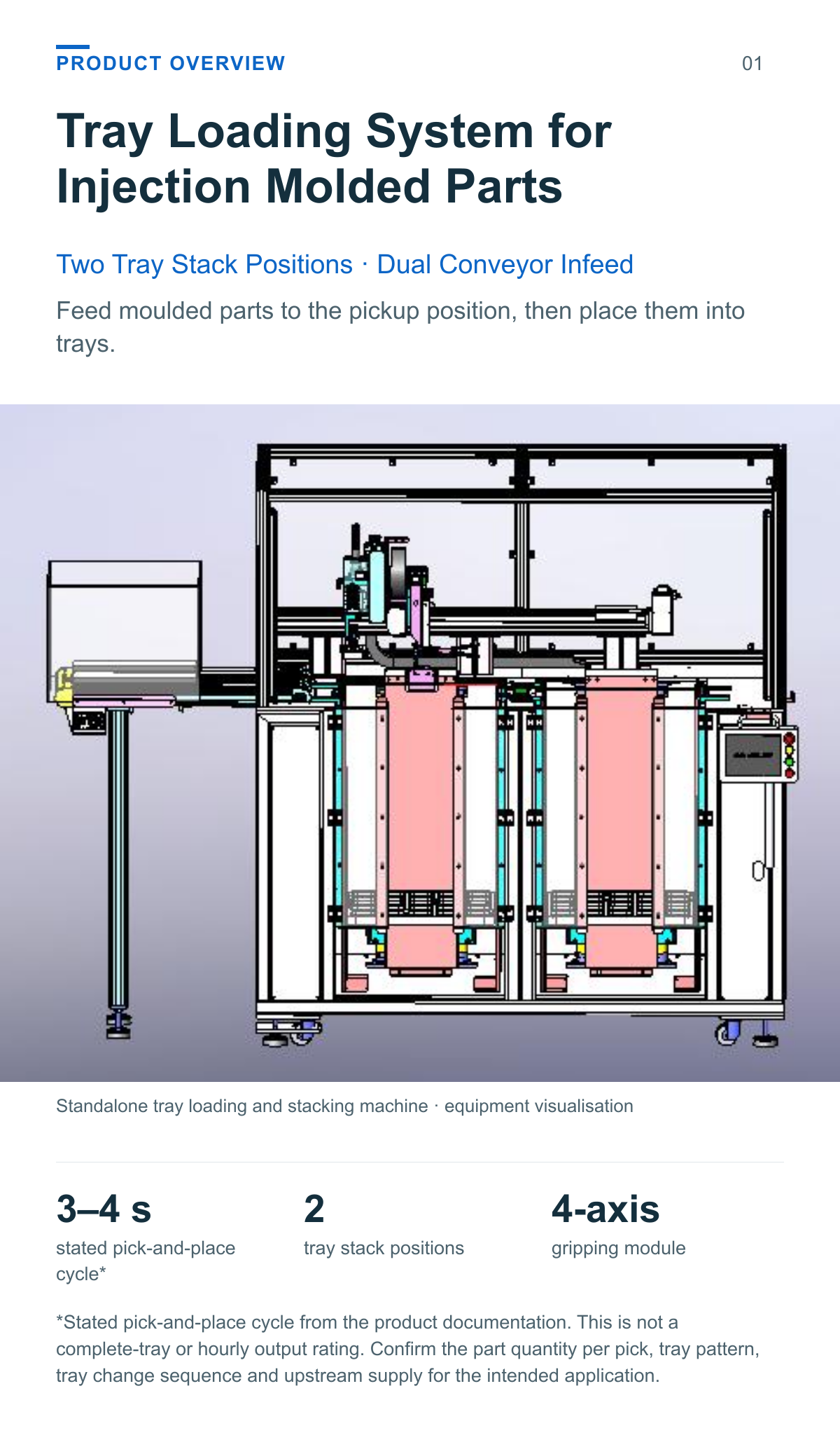
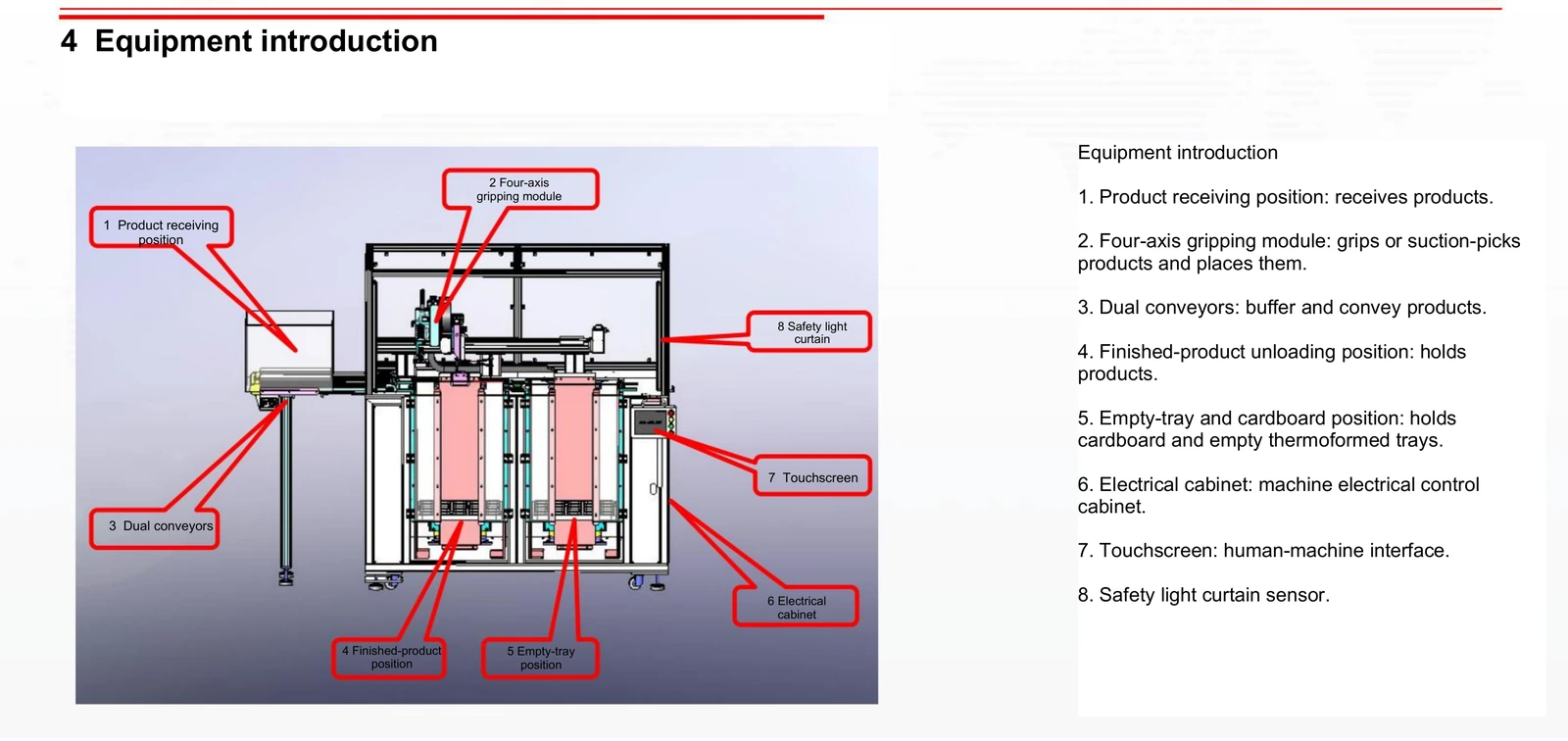
This tray loading system for injection molded parts uses dual conveyors to bring products to a four-axis gripping module. The module places parts in sequence in thermoformed trays and transfers an interlayer sheet and an empty tray when the active tray is full.
3–4 s stated pick-and-place cycle*
2 tray stack positions
4-axis gripping module
*Stated pick-and-place cycle from the product documentation. This is not a complete-tray or hourly output rating. Confirm the part quantity per pick, tray pattern, tray change sequence and upstream supply for the intended application.
From injection moulded parts to organised trays
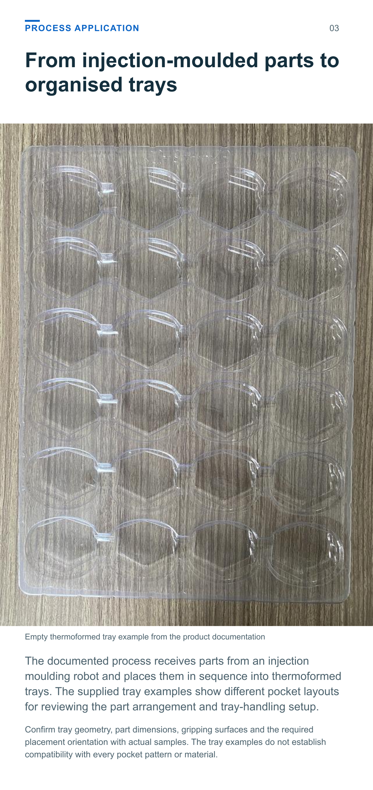
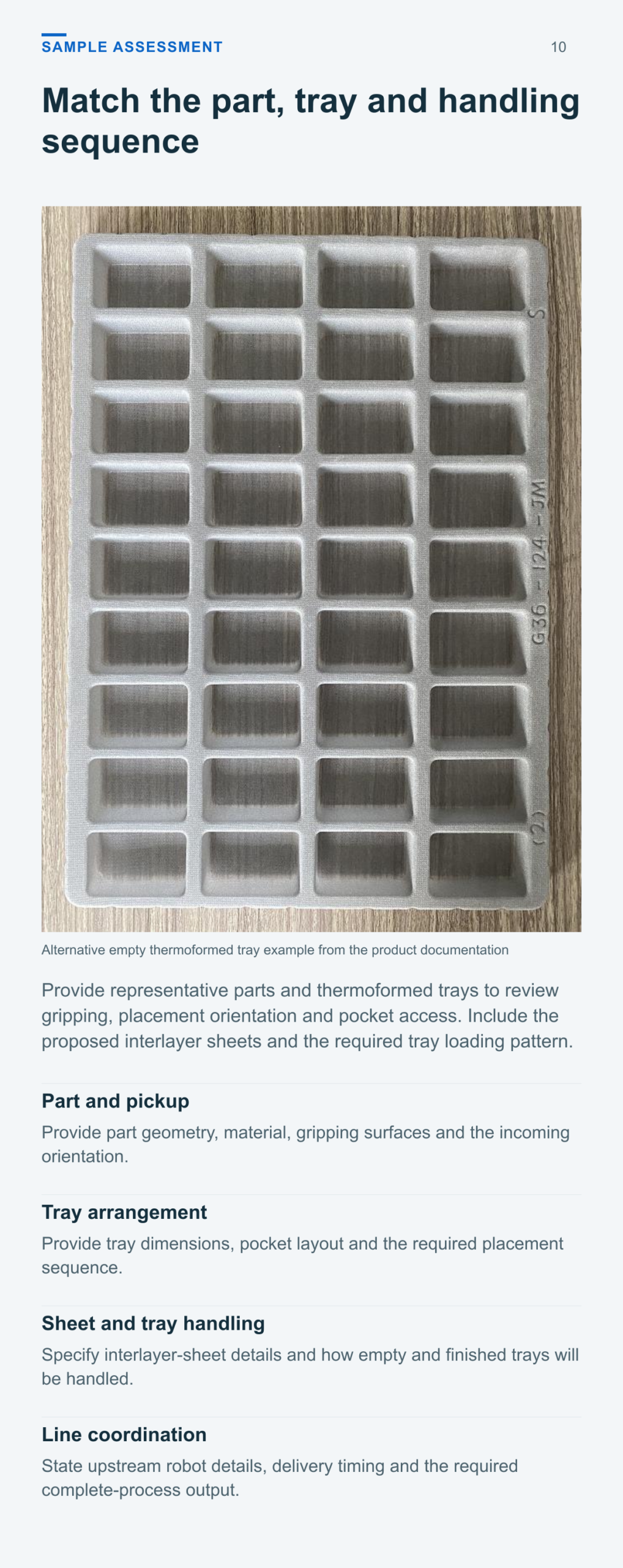
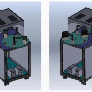
The documented process receives parts from an injection moulding robot and places them in sequence into thermoformed trays. The supplied tray examples show different pocket layouts for reviewing the part arrangement and tray-handling setup.
Receive place and prepare the next tray
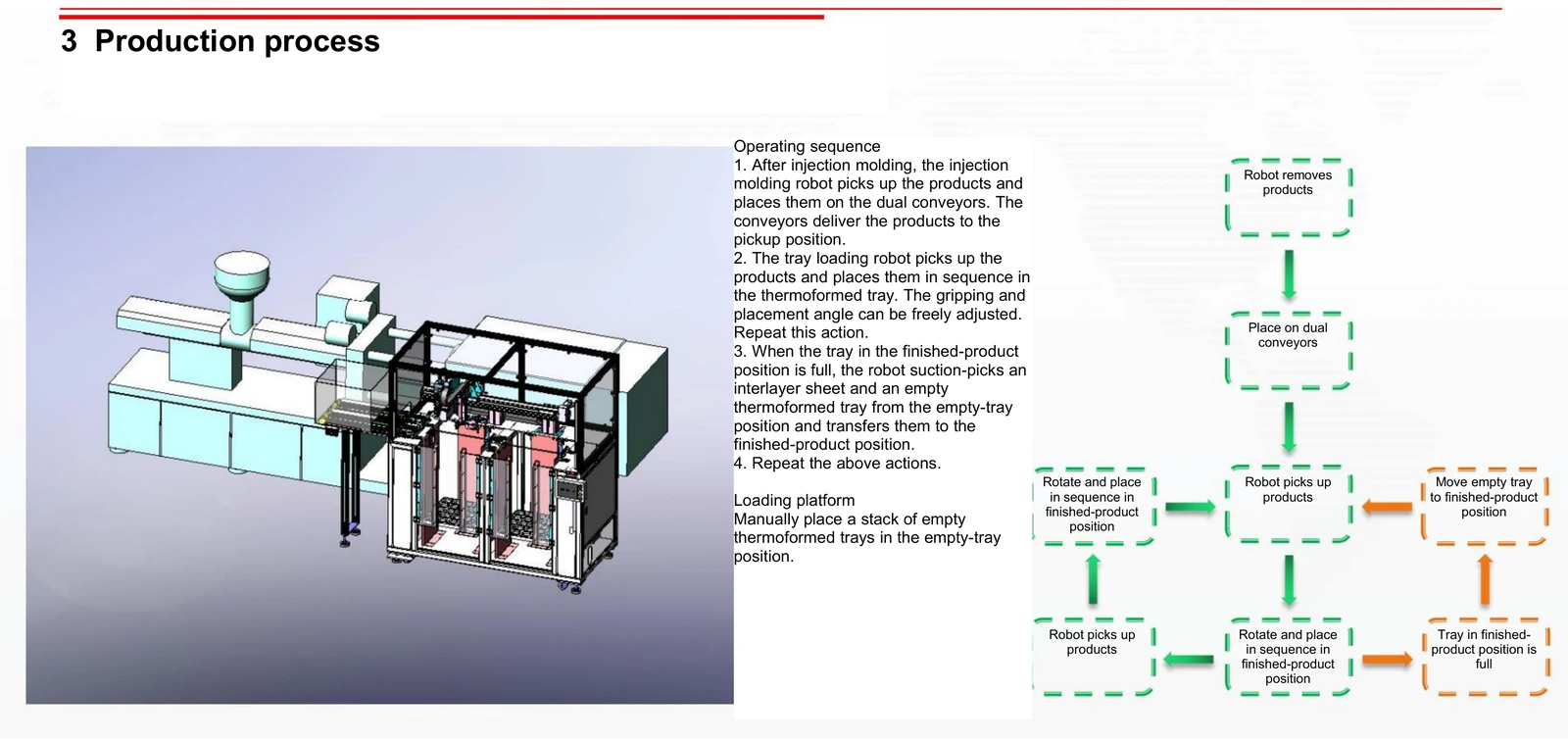
An operator supplies a stack of empty thermoformed trays to the empty-tray position. The documented production sequence then connects conveyor infeed, part placement and tray handling.
Receive moulded parts The injection moulding robot places products onto the dual conveyors, which deliver them to the tray loader’s pickup position.
Pick and place in sequence The four-axis gripping module grips or suction-picks the parts and places them into the thermoformed tray. The gripping and placement angle can be adjusted.
Fill the active tray Repeat part placement in the required sequence until the tray in the finished-product position is full.
Transfer sheet and empty tray The module suction-picks an interlayer sheet and an empty thermoformed tray from the empty-tray position and transfers them to the finished-product position. The sequence then repeats.
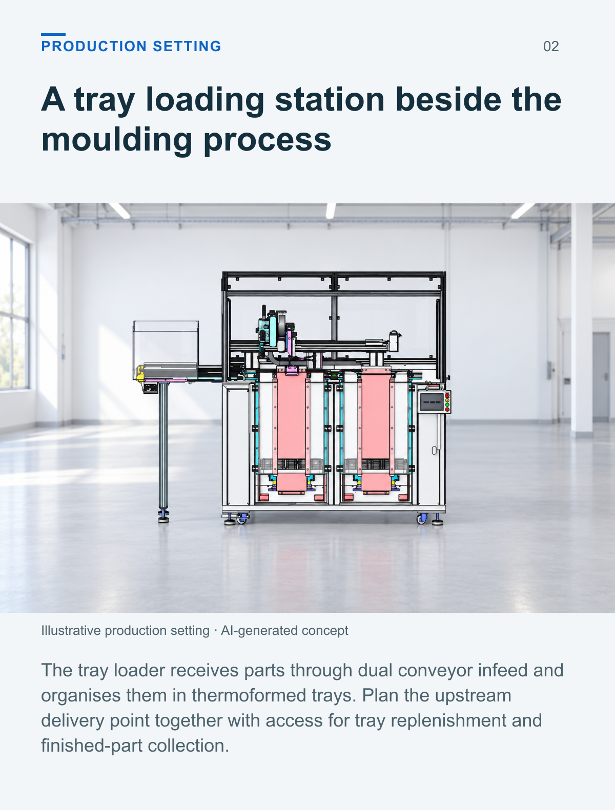
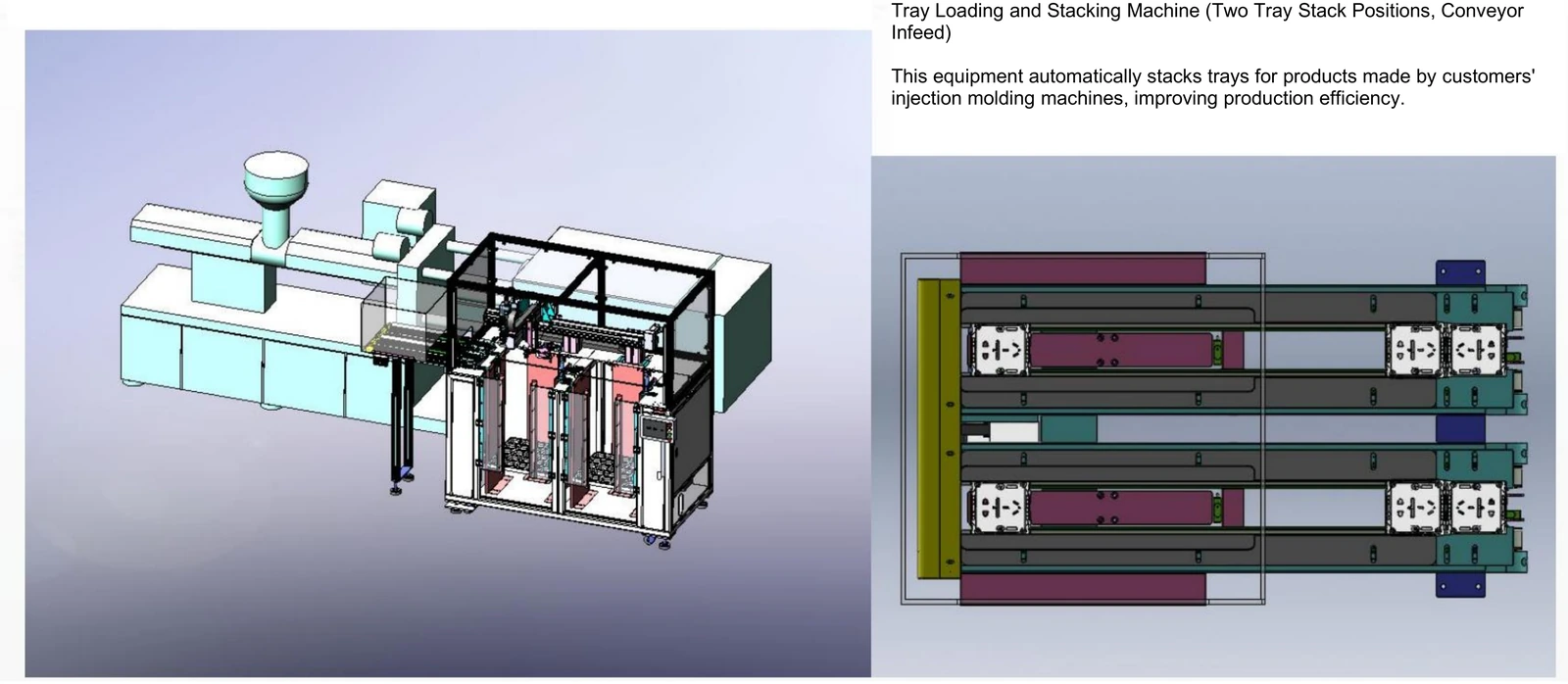
A tray loading station beside the moulding process
The tray loader receives parts through dual conveyor infeed and organises them in thermoformed trays. Plan the upstream delivery point together with access for tray replenishment and finished-part collection.
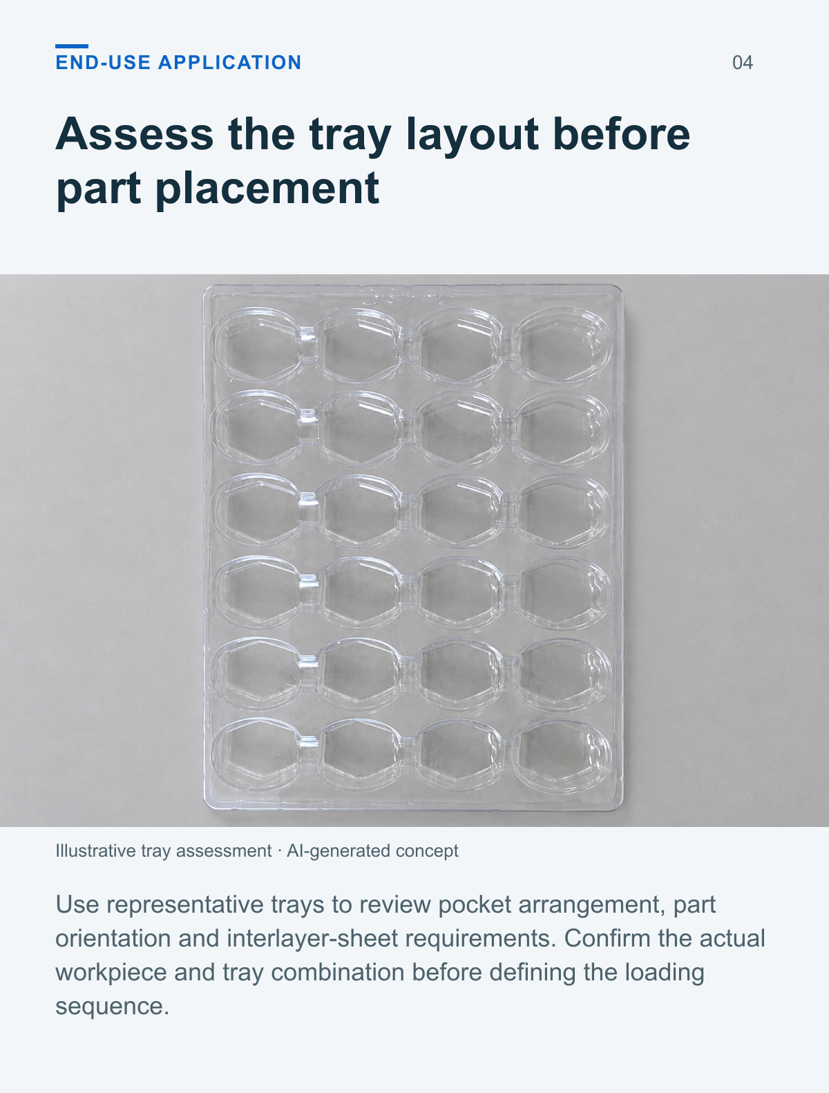
Assess the tray layout before part placement
Use representative trays to review pocket arrangement, part orientation and interlayer-sheet requirements. Confirm the actual workpiece and tray combination before defining the loading sequence.
Part loading and tray handling in one layout
Dual conveyor infeed
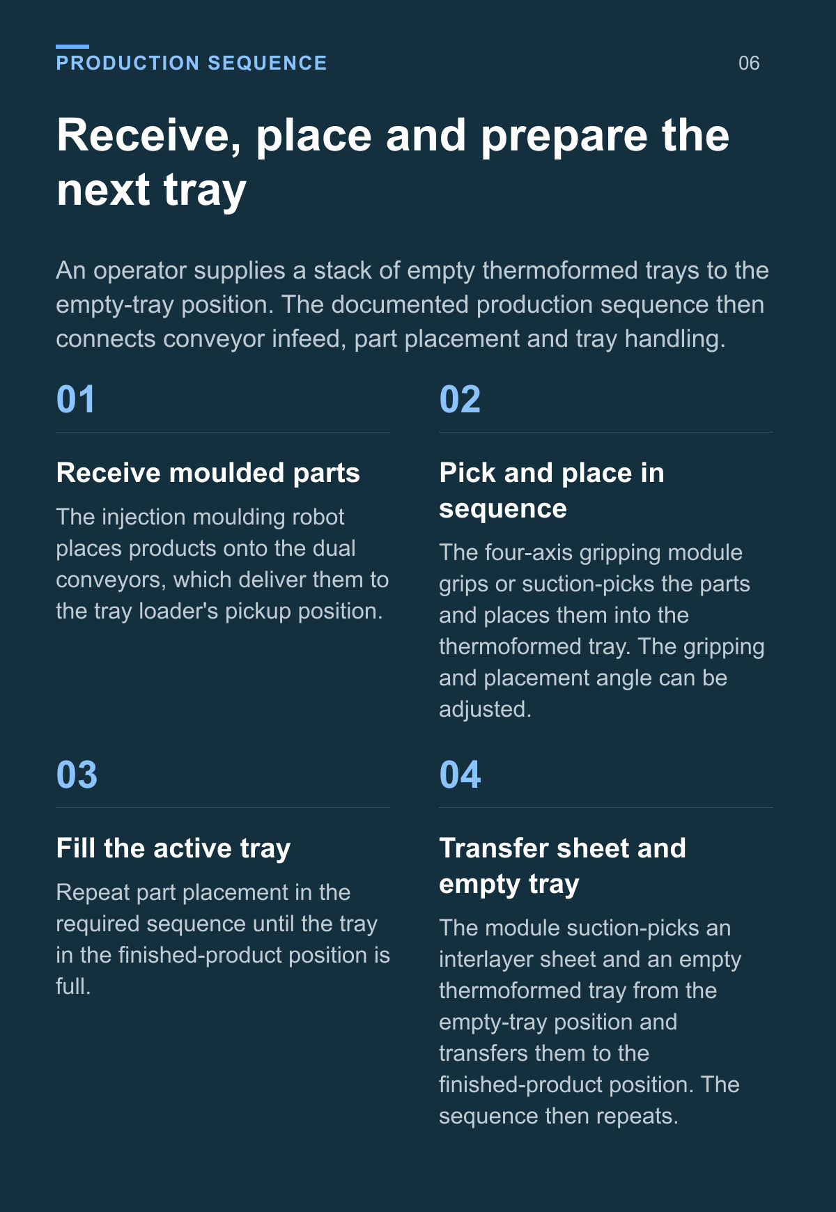
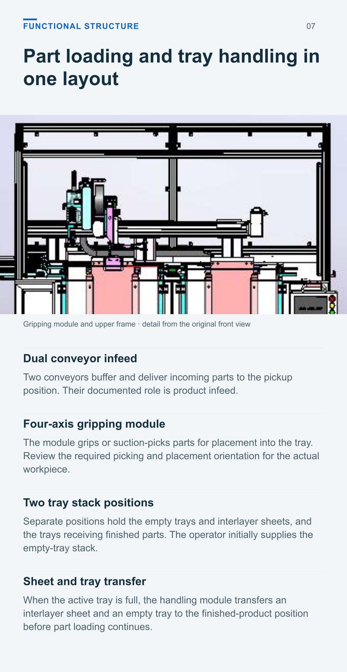
Two conveyors buffer and deliver incoming parts to the pickup position. Their documented role is product infeed.
Four axis gripping module
The module grips or suction-picks parts for placement into the tray. Review the required picking and placement orientation for the actual workpiece.
Two tray stack positions
Separate positions hold the empty trays and interlayer sheets, and the trays receiving finished parts. The operator initially supplies the empty-tray stack.
Sheet and tray transfer
When the active tray is full, the handling module transfers an interlayer sheet and an empty tray to the finished-product position before part loading continues.
Review the receiving and placement layout
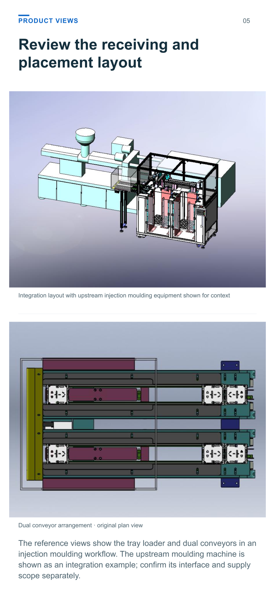
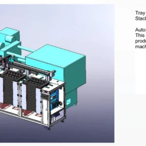
The reference views show the tray loader and dual conveyors in an injection moulding workflow. The upstream moulding machine is shown as an integration example; confirm its interface and supply scope separately.
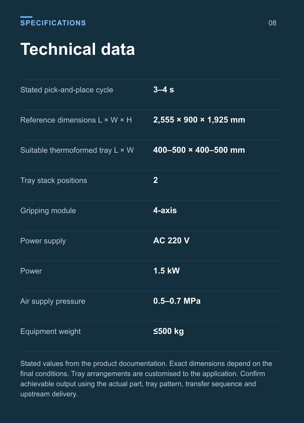
Technical data
| Parameter | Value |
|---|---|
| Stated pick-and-place cycle | 3–4 s |
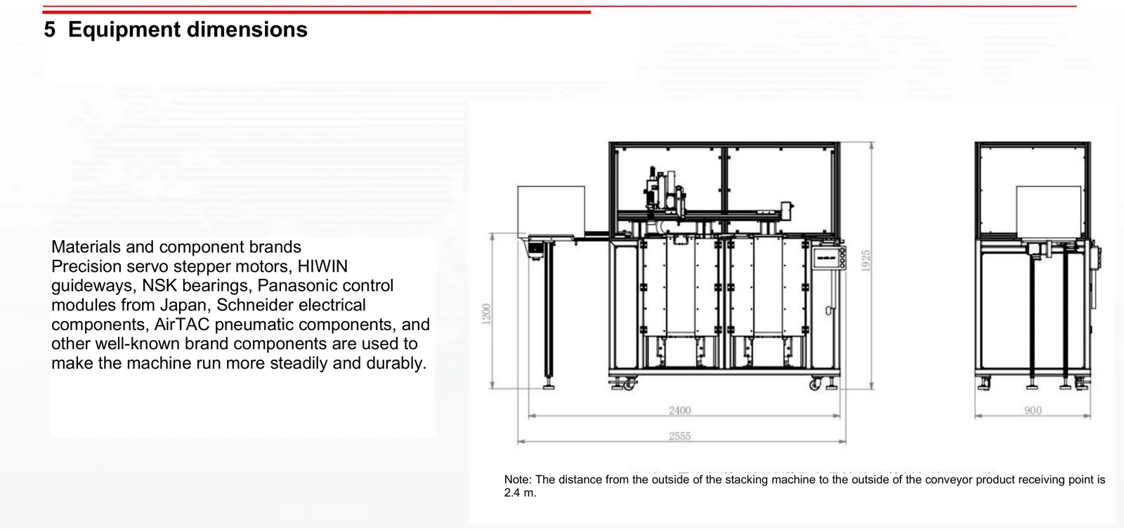
| Reference dimensions L × W × H | 2,555 × 900 × 1,925 mm |
| Suitable thermoformed tray L × W | 400–500 × 400–500 mm |
| Tray stack positions | 2 |
| Gripping module | 4-axis |
| Power supply | AC 220 V |
| Power | 1.5 kW |
| Air supply pressure | 0.5–0.7 MPa |
| Equipment weight | ≤500 kg |
Stated values from the product documentation. Exact dimensions depend on the final conditions. Tray arrangements are customised to the application. Confirm achievable output using the actual part, tray pattern, transfer sequence and upstream delivery.
Connect the moulding cell to the tray loader
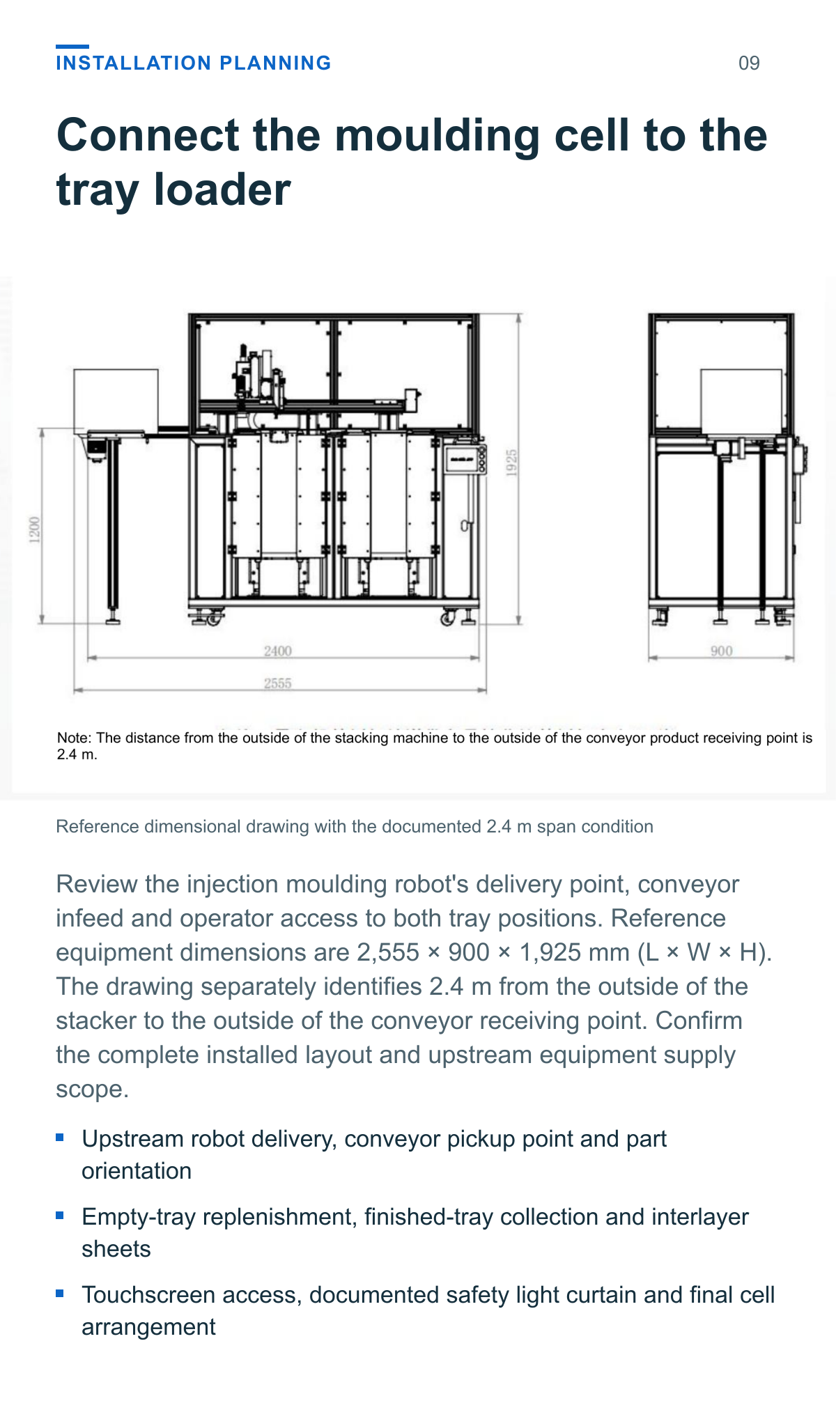
Review the injection moulding robot’s delivery point, conveyor infeed and operator access to both tray positions. Reference equipment dimensions are 2,555 × 900 × 1,925 mm (L × W × H). The drawing separately identifies 2.4 m from the outside of the stacker to the outside of the conveyor receiving point. Confirm the complete installed layout and upstream equipment supply scope.
- Upstream robot delivery, conveyor pickup point and part orientation
- Empty-tray replenishment, finished-tray collection and interlayer sheets
- Touchscreen access, documented safety light curtain and final cell arrangement
Match the part tray and handling sequence
Provide representative parts and thermoformed trays to review gripping, placement orientation and pocket access. Include the proposed interlayer sheets and the required tray loading pattern.
Part and pickup
Provide part geometry, material, gripping surfaces and the incoming orientation.
Tray arrangement
Provide tray dimensions, pocket layout and the required placement sequence.
Sheet and tray handling
Specify interlayer-sheet details and how empty and finished trays will be handled.
Line coordination
State upstream robot details, delivery timing and the required complete-process output.
Application questions
What do the dual conveyors carry
They buffer and feed incoming products from the injection moulding robot to the tray loader’s pickup position. The documented configuration is conveyor infeed.
What do the two tray stack positions do
One position supplies empty thermoformed trays and interlayer sheets. The other receives trays being loaded with parts. An operator initially places a stack of empty trays in the supply position.
Does the 3 to 4 second cycle mean a complete tray is filled
It is the stated pick-and-place cycle. Complete-tray and hourly output depend on the part quantity per pick, tray layout, sheet and tray handling, and upstream supply. Confirm these with the intended application.
Which trays can be assessed
The source specifies thermoformed trays with length and width each in the 400–500 mm range, customised to requirements. Provide tray drawings, actual samples, pocket layout, part details and interlayer-sheet requirements for review.
Define your conveyor fed tray loading process
Provide moulded-part samples, tray drawings, interlayer-sheet details and upstream robot information to review the pickup arrangement, placement pattern and required production output.
Product views and application details