Tray Loading System for Injection Molded Parts
Two Tray Stack Positions Conveyor Discharge
Load parts into trays and discharge the stack at the set tray count.
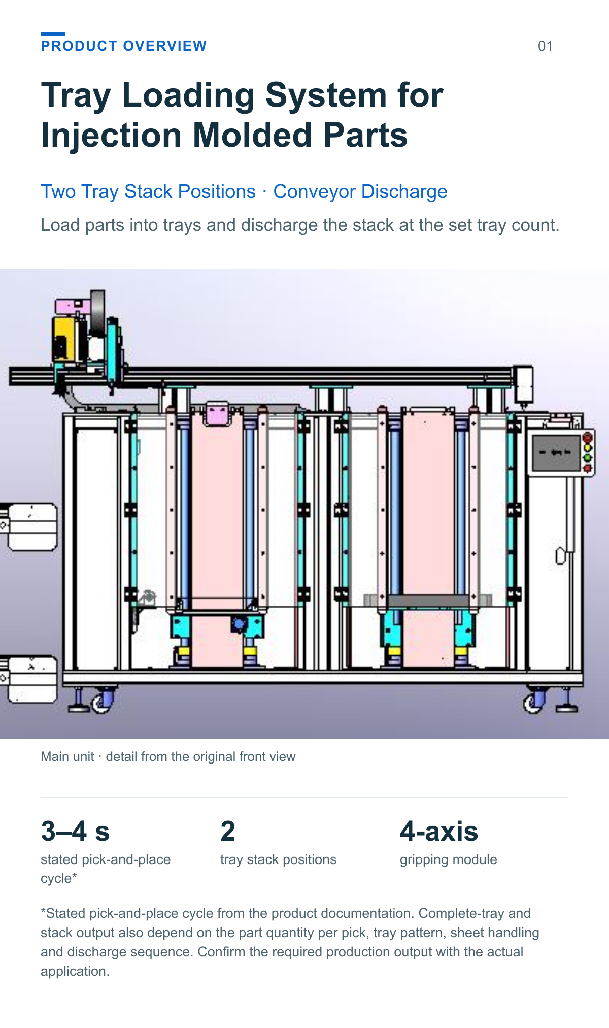
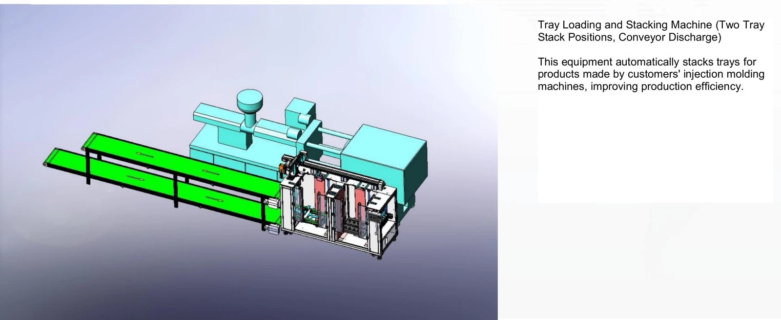
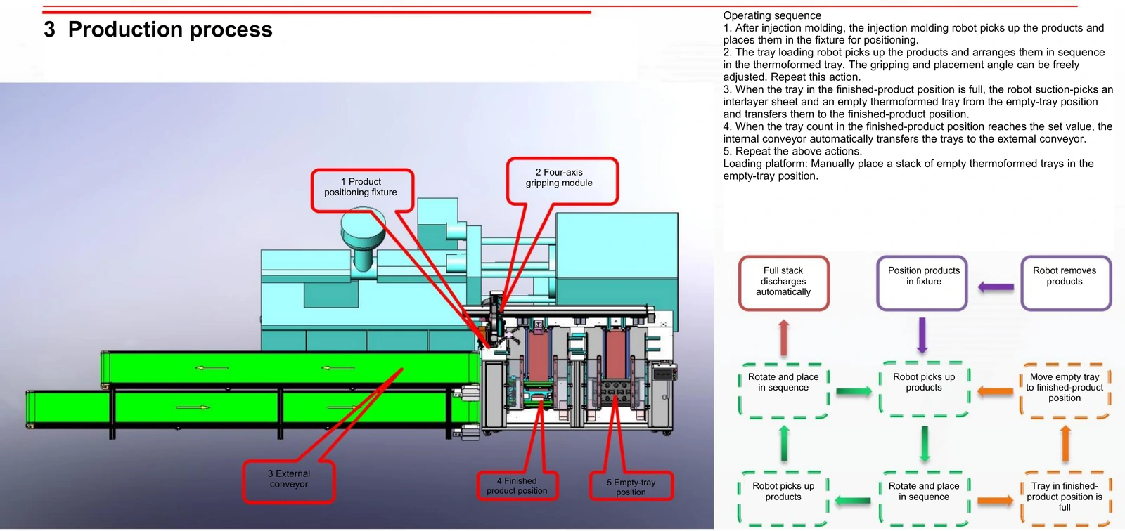
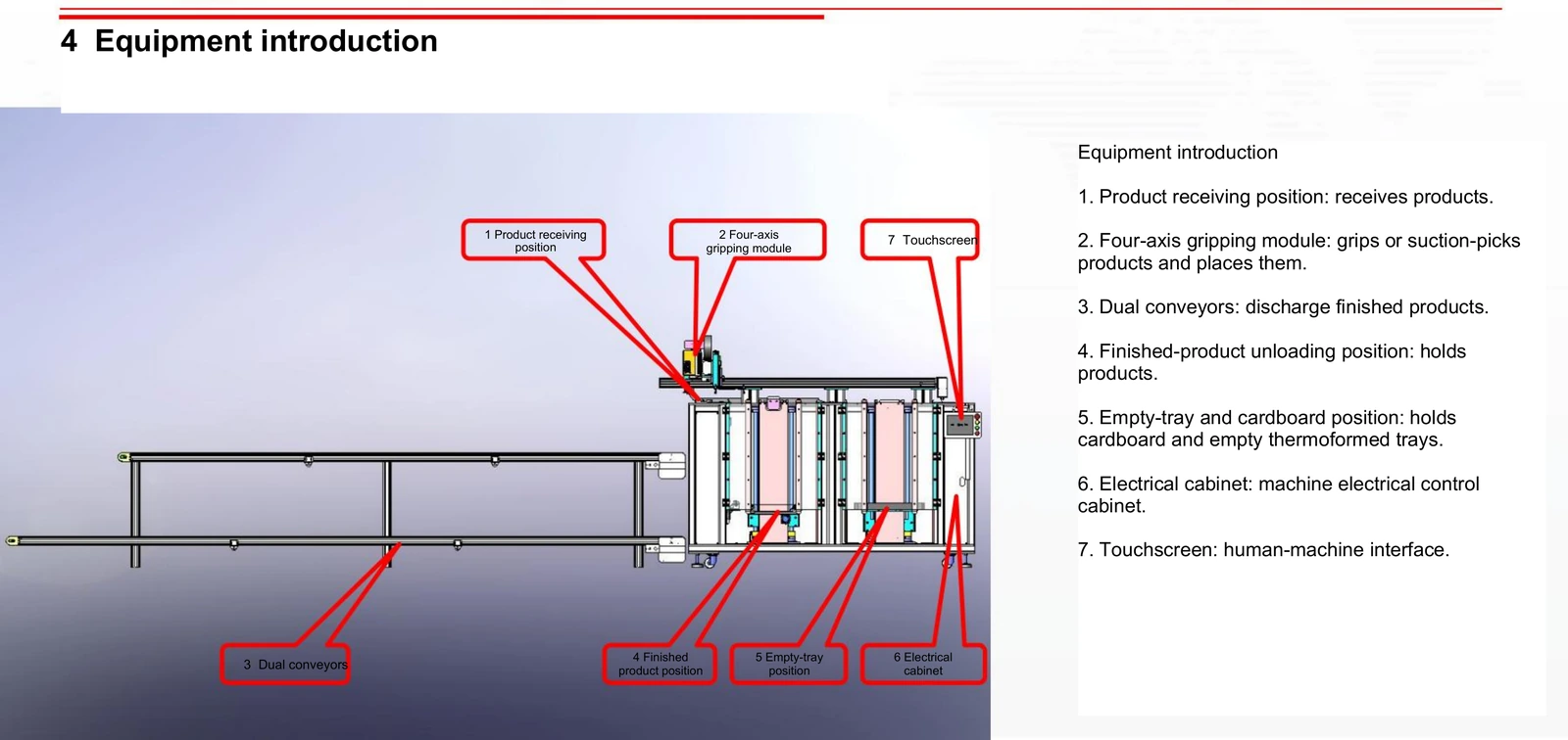
This tray loading system for injection molded parts receives products at a positioning fixture. A four-axis gripping module places the parts into thermoformed trays. When the finished-tray count reaches the set value, the internal conveyor transfers the trays to an external conveyor.
3–4 s stated pick-and-place cycle*
2 tray stack positions
4-axis gripping module
*Stated pick-and-place cycle from the product documentation. Complete-tray and stack output also depend on the part quantity per pick, tray pattern, sheet handling and discharge sequence. Confirm the required production output with the actual application.
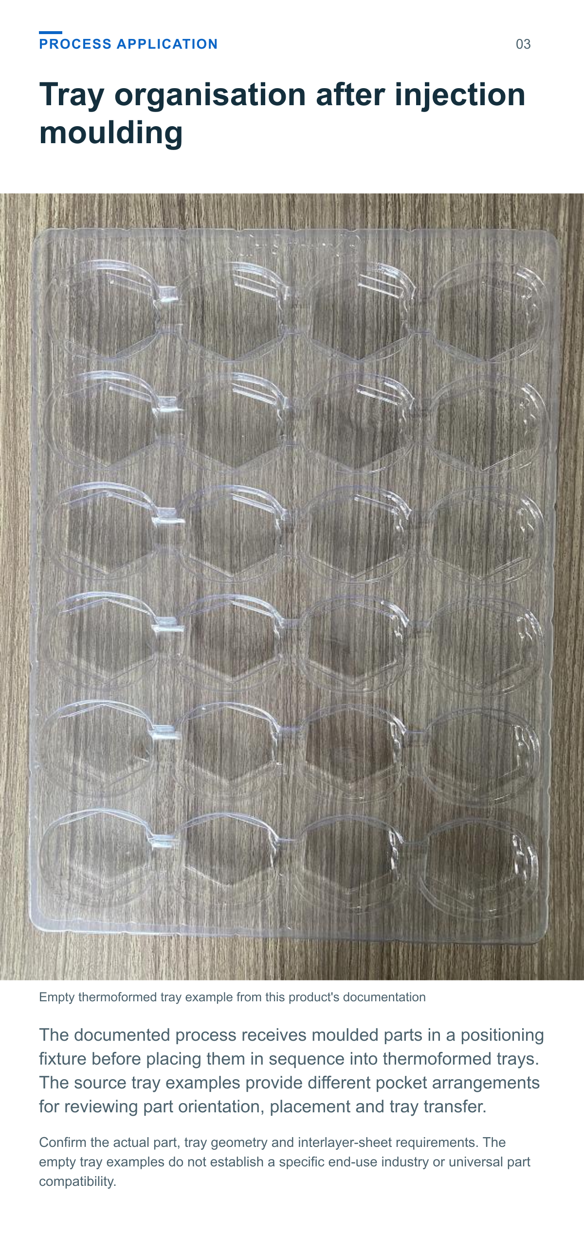
Tray organisation after injection moulding
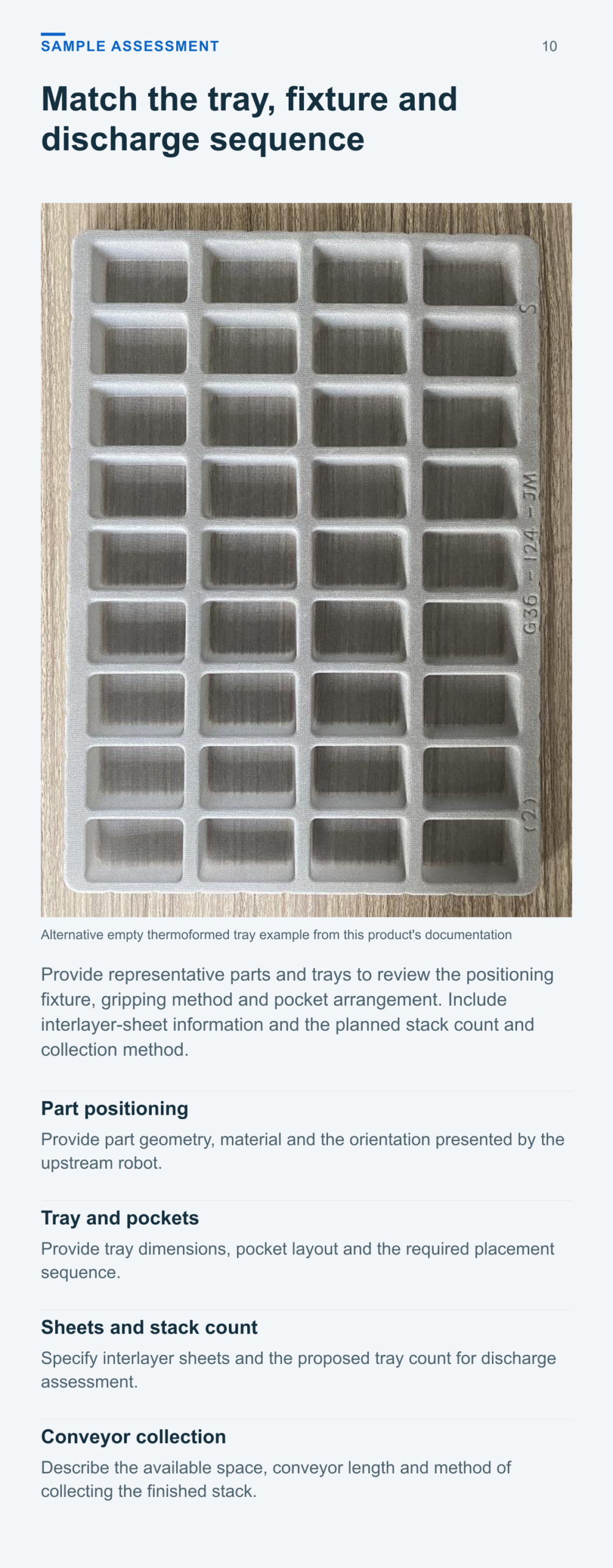
The documented process receives moulded parts in a positioning fixture before placing them in sequence into thermoformed trays. The source tray examples provide different pocket arrangements for reviewing part orientation, placement and tray transfer.
Position parts load trays and discharge the stack
An operator places a stack of empty thermoformed trays in the empty-tray position. Product delivery is through a positioning fixture; the conveyors handle the documented finished-tray discharge.
Receive and position parts The injection moulding robot removes the products and places them in the fixture for positioning.
Pick and place into the tray The four-axis gripping module grips or suction-picks the parts and places them in sequence. The gripping and placement angle can be adjusted.
Prepare successive trays When the active tray is full, the module suction-picks an interlayer sheet and an empty tray from the supply position and transfers them to the finished-product position.
Discharge at the set tray count When the tray count in the finished-product position reaches the set value, the internal conveyor automatically transfers the trays to the external conveyor. The sequence repeats.
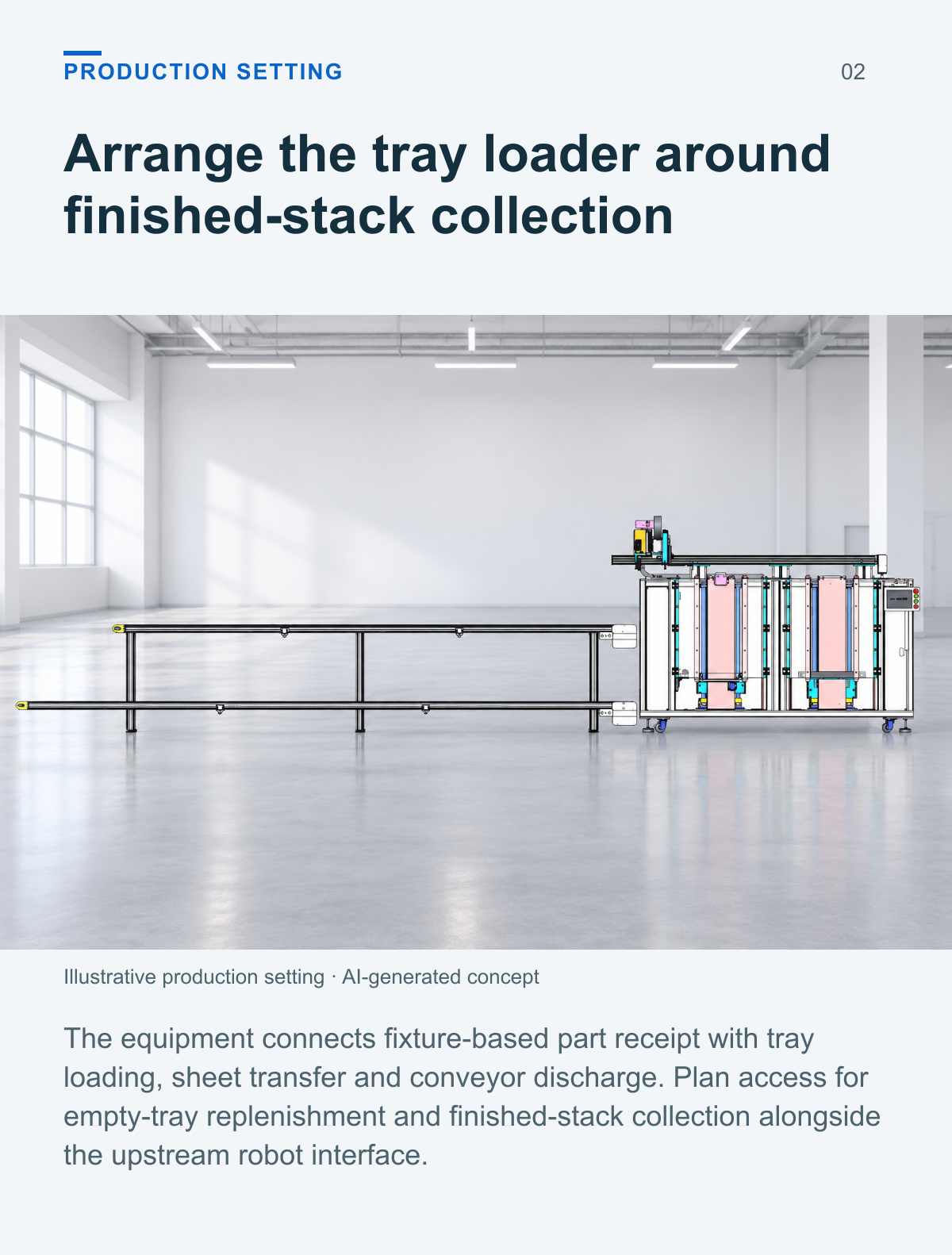
Arrange the tray loader around finished stack collection
The equipment connects fixture-based part receipt with tray loading, sheet transfer and conveyor discharge. Plan access for empty-tray replenishment and finished-stack collection alongside the upstream robot interface.
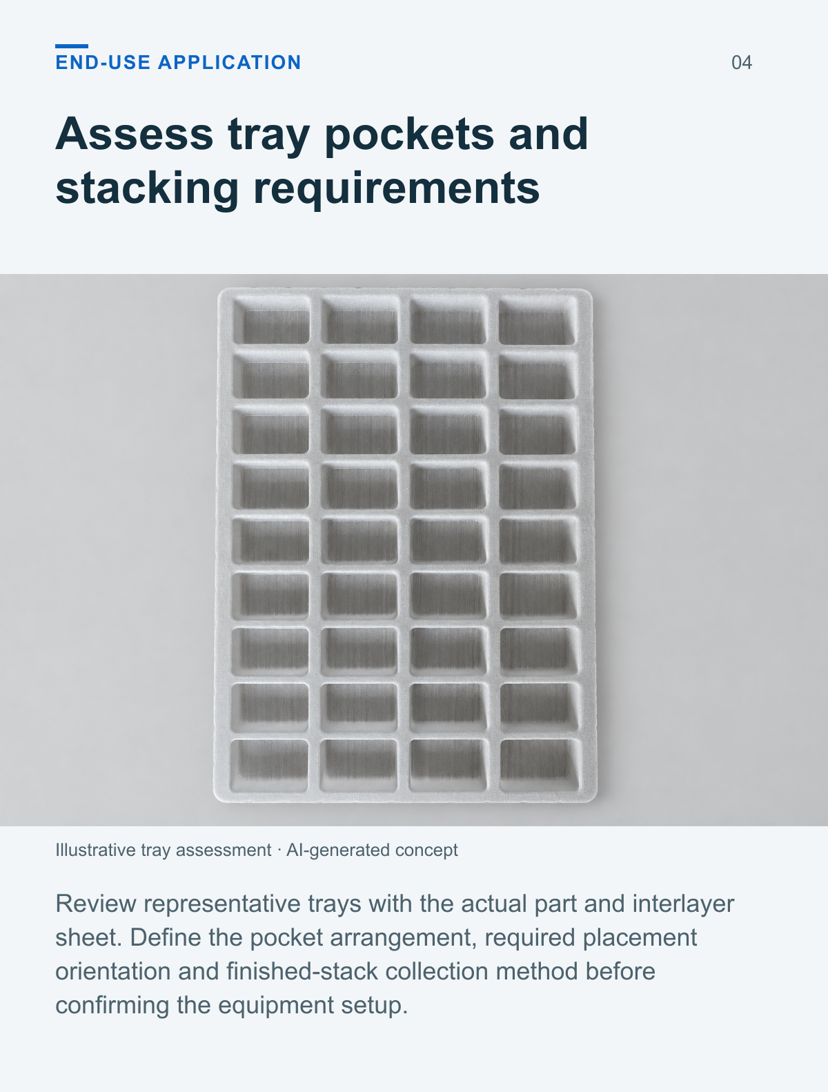
Assess tray pockets and stacking requirements
Review representative trays with the actual part and interlayer sheet. Define the pocket arrangement, required placement orientation and finished-stack collection method before confirming the equipment setup.
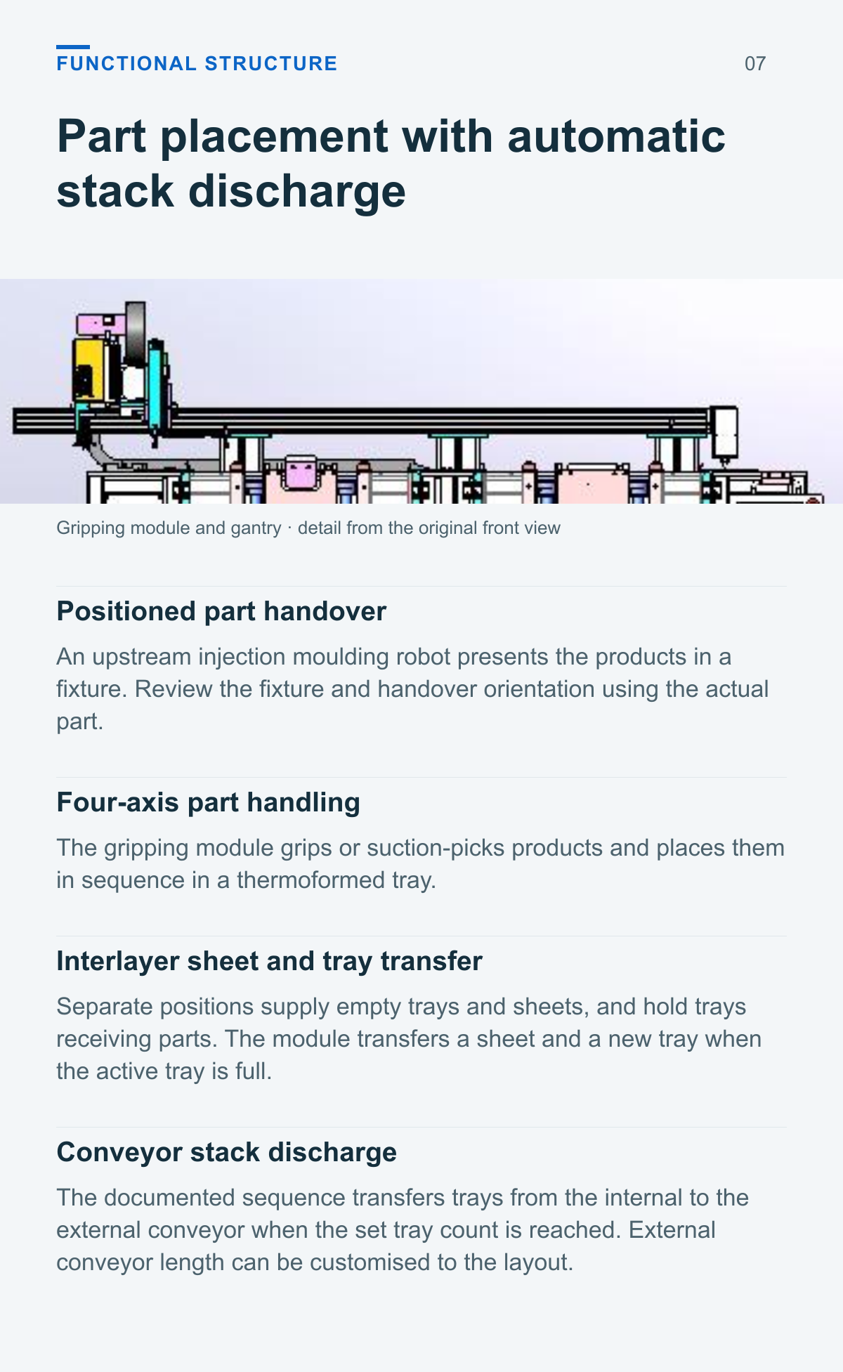
Part placement with automatic stack discharge
Positioned part handover
An upstream injection moulding robot presents the products in a fixture. Review the fixture and handover orientation using the actual part.
Four axis part handling
The gripping module grips or suction-picks products and places them in sequence in a thermoformed tray.
Interlayer sheet and tray transfer
Separate positions supply empty trays and sheets, and hold trays receiving parts. The module transfers a sheet and a new tray when the active tray is full.
Conveyor stack discharge
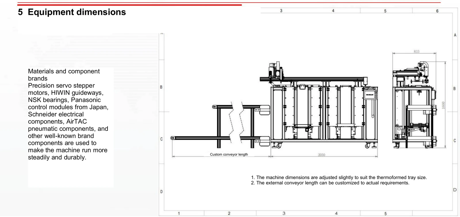
The documented sequence transfers trays from the internal to the external conveyor when the set tray count is reached. External conveyor length can be customised to the layout.
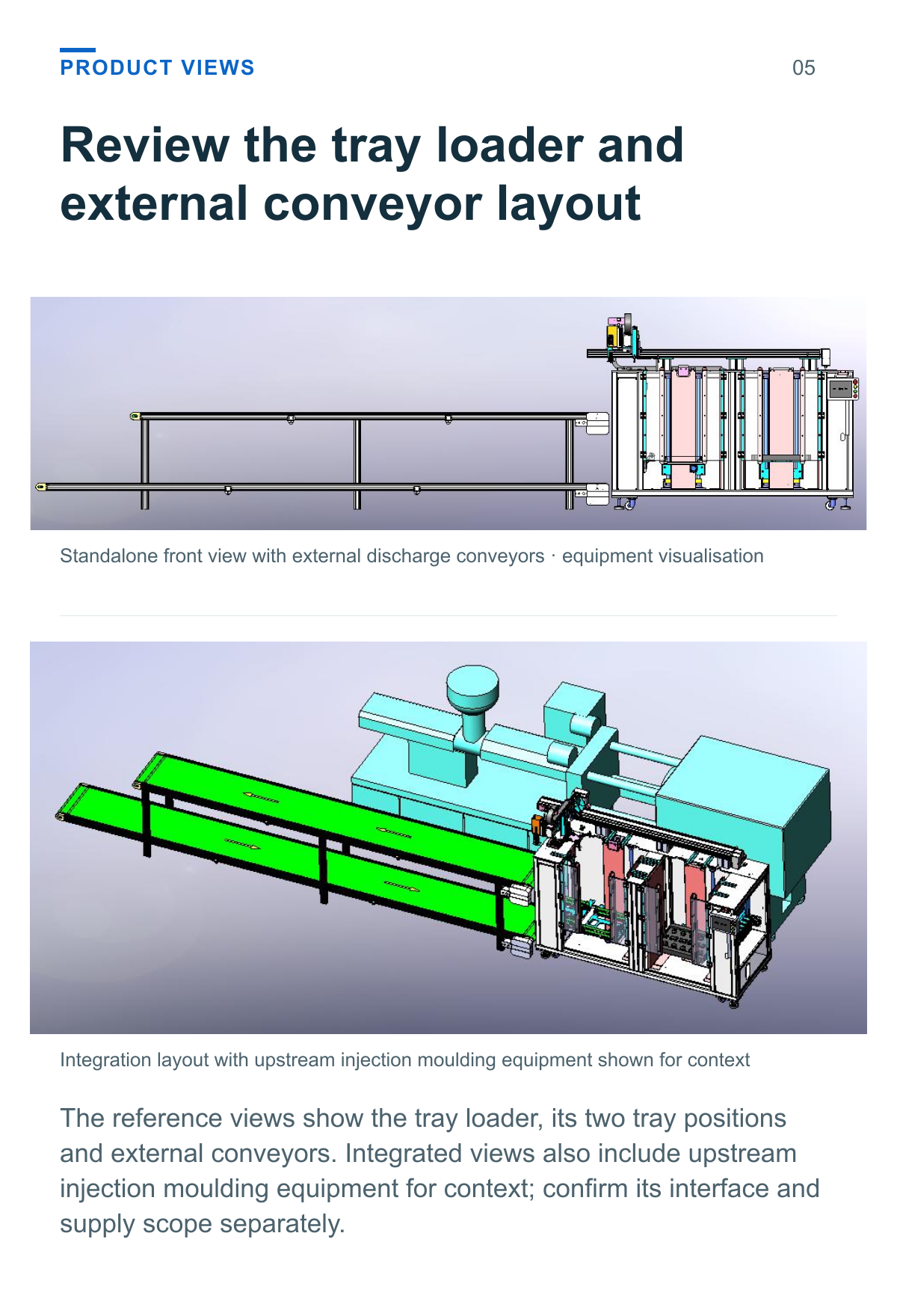
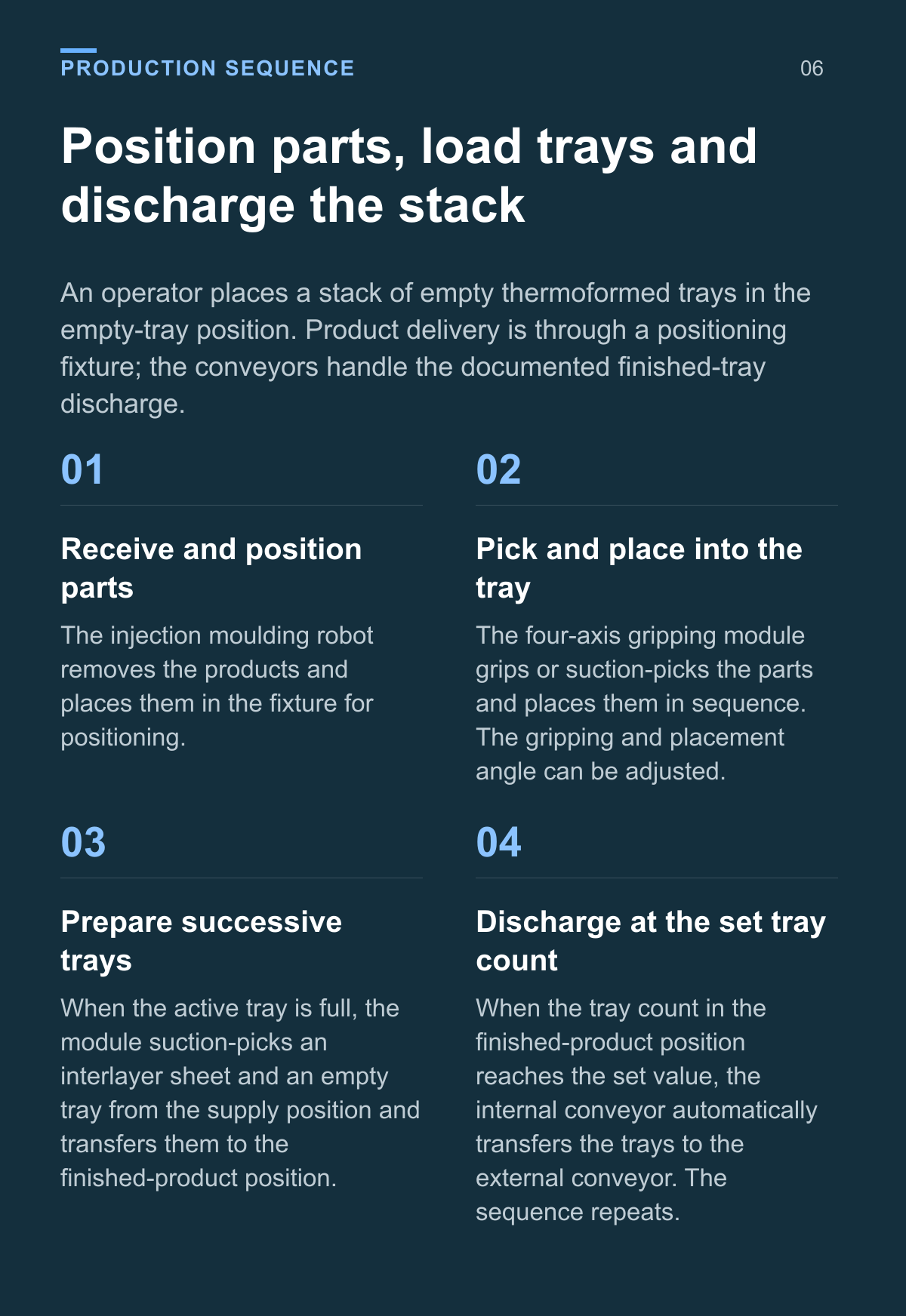
Review the tray loader and external conveyor layout
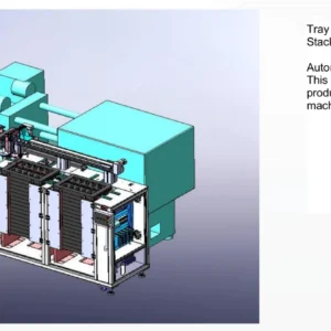
The reference views show the tray loader, its two tray positions and external conveyors. Integrated views also include upstream injection moulding equipment for context; confirm its interface and supply scope separately.
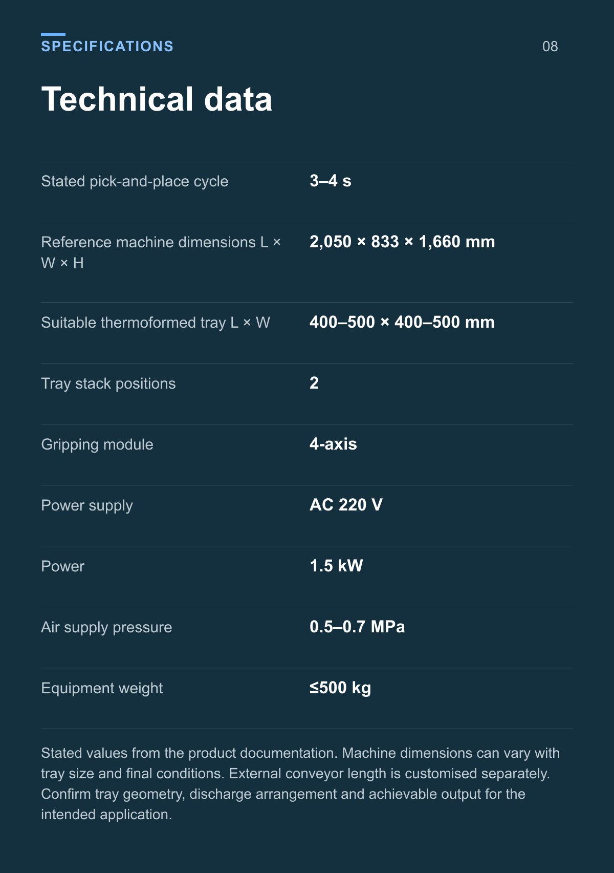
Technical data
| Parameter | Value |
|---|---|
| Stated pick-and-place cycle | 3–4 s |
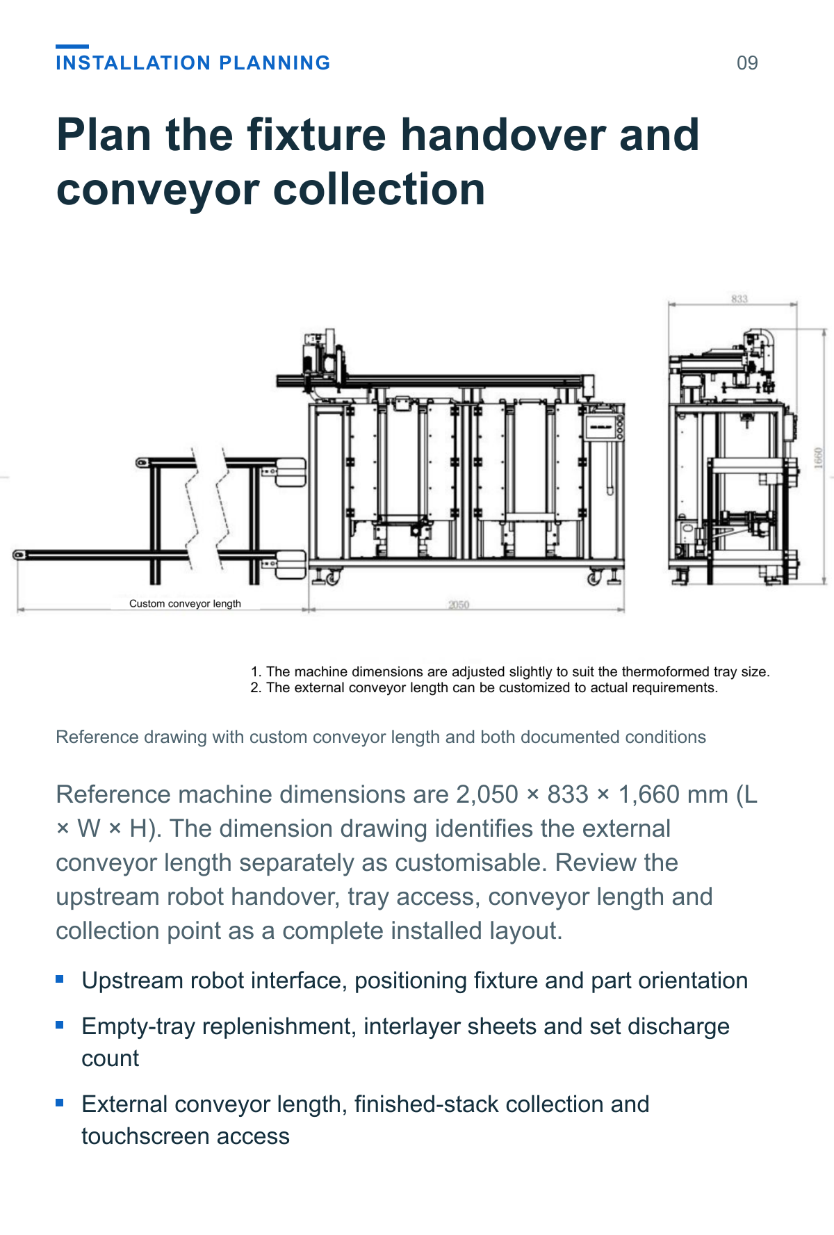
| Reference machine dimensions L × W × H | 2,050 × 833 × 1,660 mm |
| Suitable thermoformed tray L × W | 400–500 × 400–500 mm |
| Tray stack positions | 2 |
| Gripping module | 4-axis |
| Power supply | AC 220 V |
| Power | 1.5 kW |
| Air supply pressure | 0.5–0.7 MPa |
| Equipment weight | ≤500 kg |
Stated values from the product documentation. Machine dimensions can vary with tray size and final conditions. External conveyor length is customised separately. Confirm tray geometry, discharge arrangement and achievable output for the intended application.
Plan the fixture handover and conveyor collection
Reference machine dimensions are 2,050 × 833 × 1,660 mm (L × W × H). The dimension drawing identifies the external conveyor length separately as customisable. Review the upstream robot handover, tray access, conveyor length and collection point as a complete installed layout.
- Upstream robot interface, positioning fixture and part orientation
- Empty-tray replenishment, interlayer sheets and set discharge count
- External conveyor length, finished-stack collection and touchscreen access
Match the tray fixture and discharge sequence
Provide representative parts and trays to review the positioning fixture, gripping method and pocket arrangement. Include interlayer-sheet information and the planned stack count and collection method.
Part positioning
Provide part geometry, material and the orientation presented by the upstream robot.
Tray and pockets
Provide tray dimensions, pocket layout and the required placement sequence.
Sheets and stack count
Specify interlayer sheets and the proposed tray count for discharge assessment.
Conveyor collection
Describe the available space, conveyor length and method of collecting the finished stack.
Application questions
How do products enter the tray loader
The documented upstream injection moulding robot places the products in a positioning fixture. The tray loader then picks and places them into the thermoformed tray.
When does the finished tray stack discharge
When the tray count in the finished-product position reaches the set value, the internal conveyor automatically transfers the trays to the external conveyor. Confirm the intended count and collection arrangement for the actual tray.
What does the 3 to 4 second value describe
It is the stated pick-and-place cycle. It does not specify a complete tray or stack cycle. Assess total output with the part quantity per pick, tray pattern, sheet transfer and conveyor discharge sequence.
Can the conveyor and tray arrangement be adjusted
The source allows external conveyor length to be customised and machine dimensions to vary with the tray size. The documented tray range is 400–500 mm in both length and width; confirm the final arrangement using actual tray and part samples.
Define your tray loading and discharge process
Provide the moulded-part samples, tray drawings, interlayer-sheet details, upstream robot information and proposed discharge layout to review the complete handling sequence.
Product views and application details