Automatic Feeding and Unloading System for Pad Printing Machines
Vibratory Feeding Positioning Conveyor Unloading
Present parts to the print station and transfer them to a conveyor.
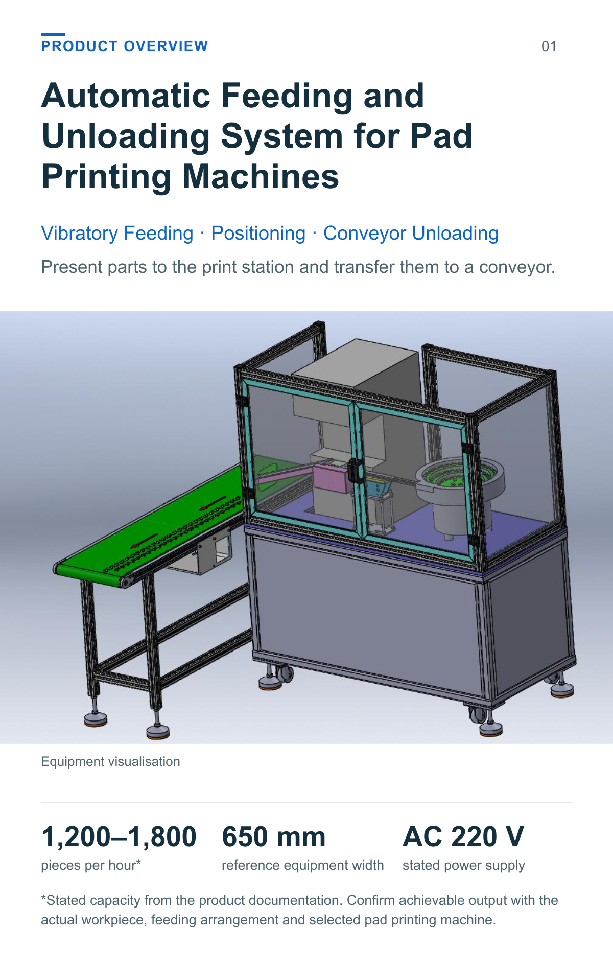
This pad printing automatic feeding system uses a vibratory bowl and linear feeder to present parts to the pad printing station. A positioning mechanism and unloading arrangement support the part-handling process around the printer.
1,200–1,800 pieces per hour*
650 mm reference equipment width
AC 220 V stated power supply
*Stated capacity from the product documentation. Confirm achievable output with the actual workpiece, feeding arrangement and selected pad printing machine.
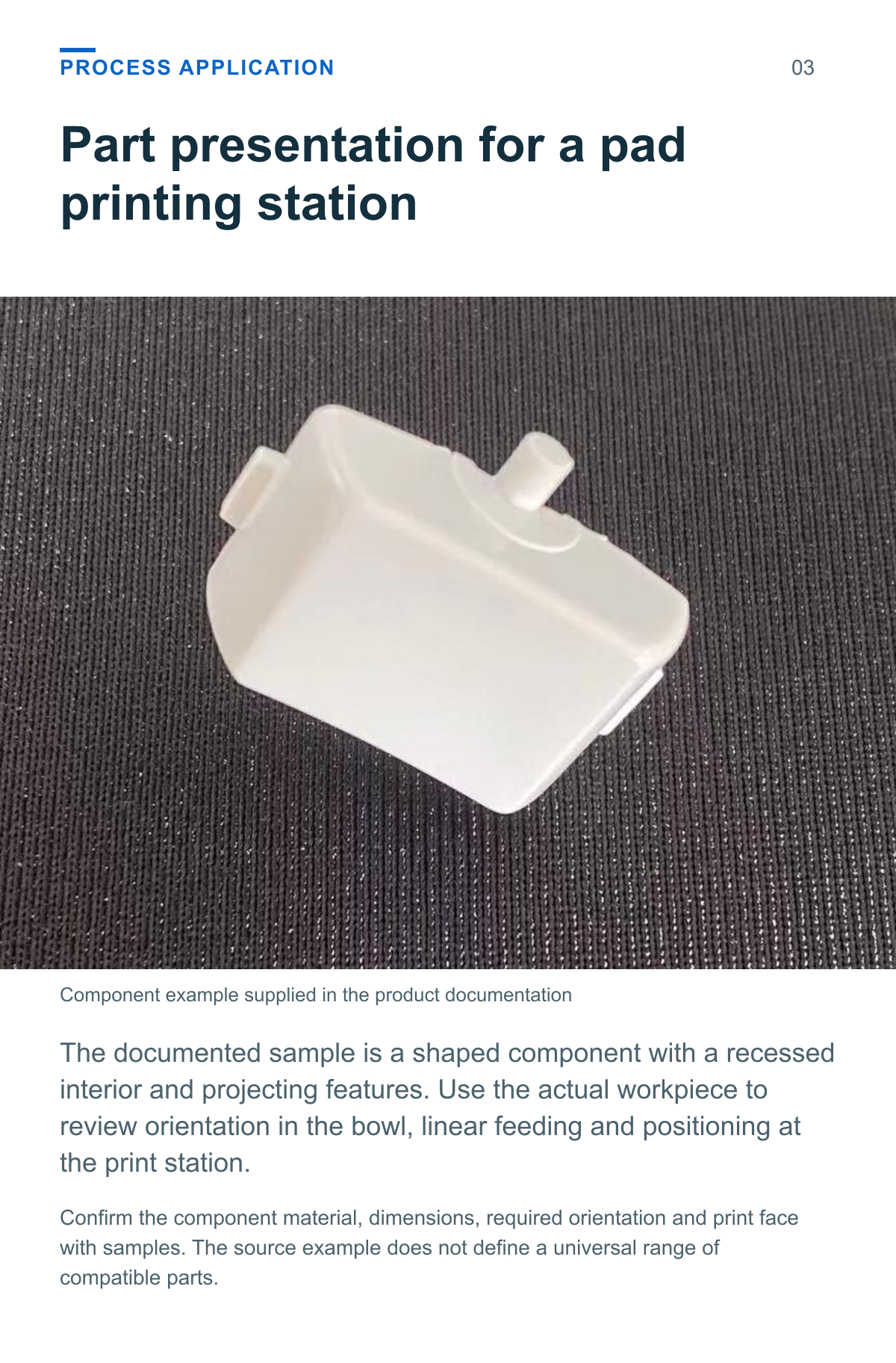
Part presentation for a pad printing station
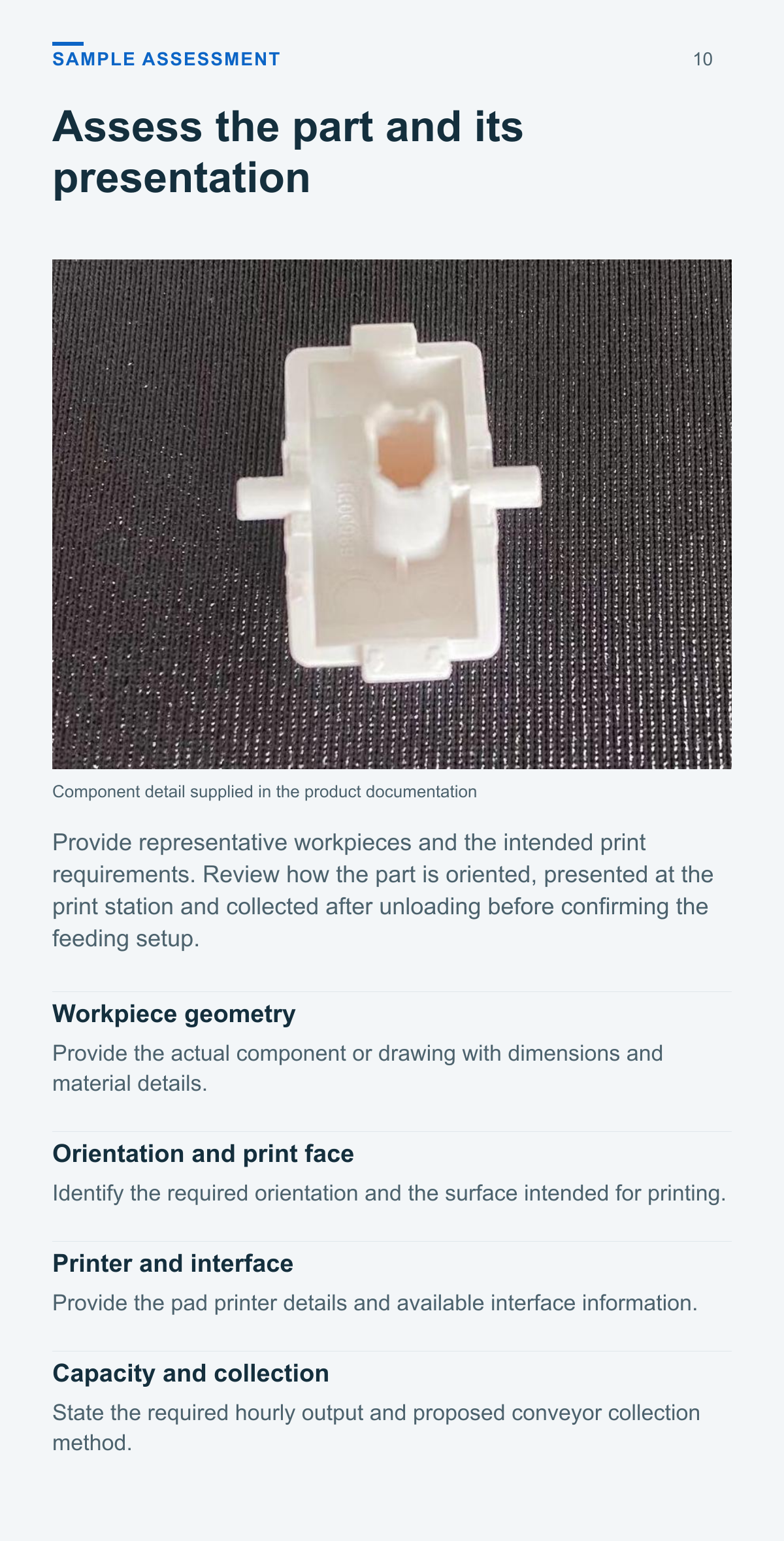
The documented sample is a shaped component with a recessed interior and projecting features. Use the actual workpiece to review orientation in the bowl, linear feeding and positioning at the print station.
Orient feed print and unload
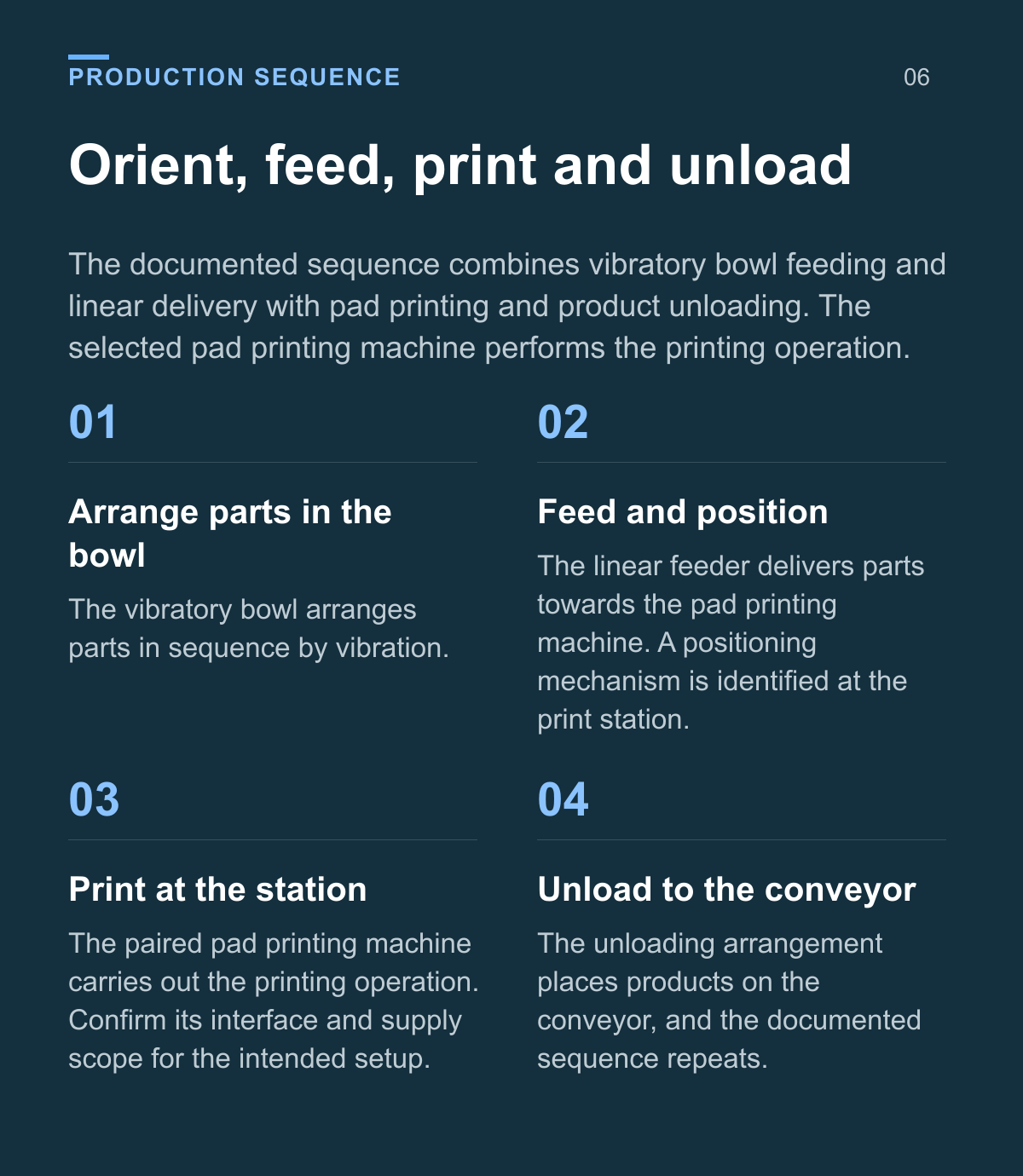
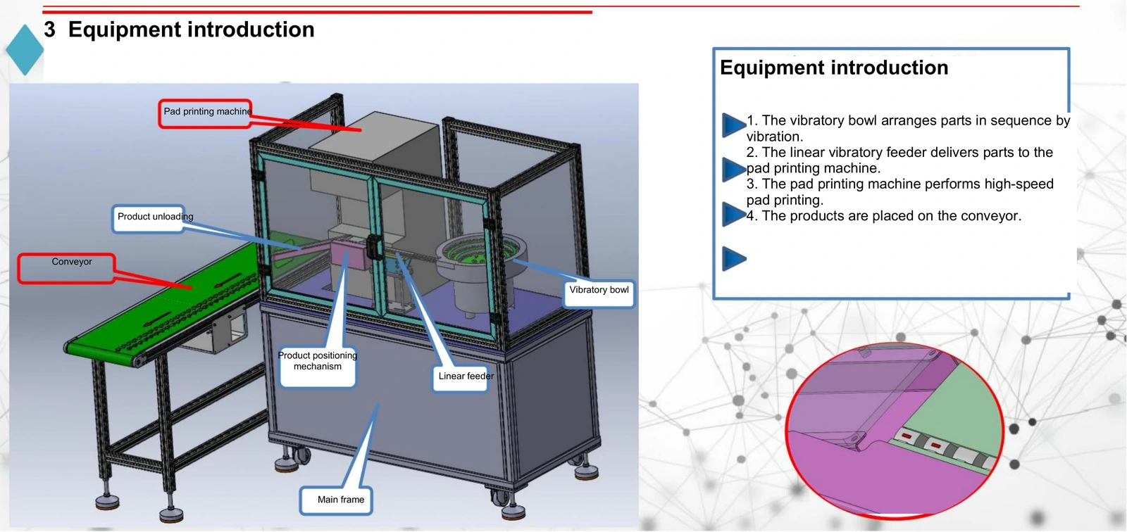
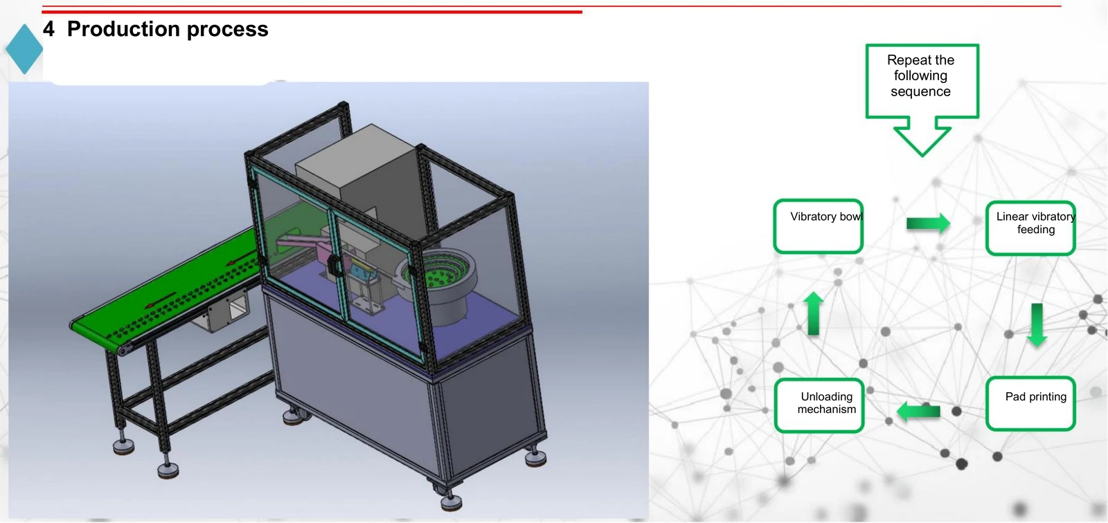
The documented sequence combines vibratory bowl feeding and linear delivery with pad printing and product unloading. The selected pad printing machine performs the printing operation.
Arrange parts in the bowl The vibratory bowl arranges parts in sequence by vibration.
Feed and position The linear feeder delivers parts towards the pad printing machine. A positioning mechanism is identified at the print station.
Print at the station The paired pad printing machine carries out the printing operation. Confirm its interface and supply scope for the intended setup.
Unload to the conveyor The unloading arrangement places products on the conveyor, and the documented sequence repeats.
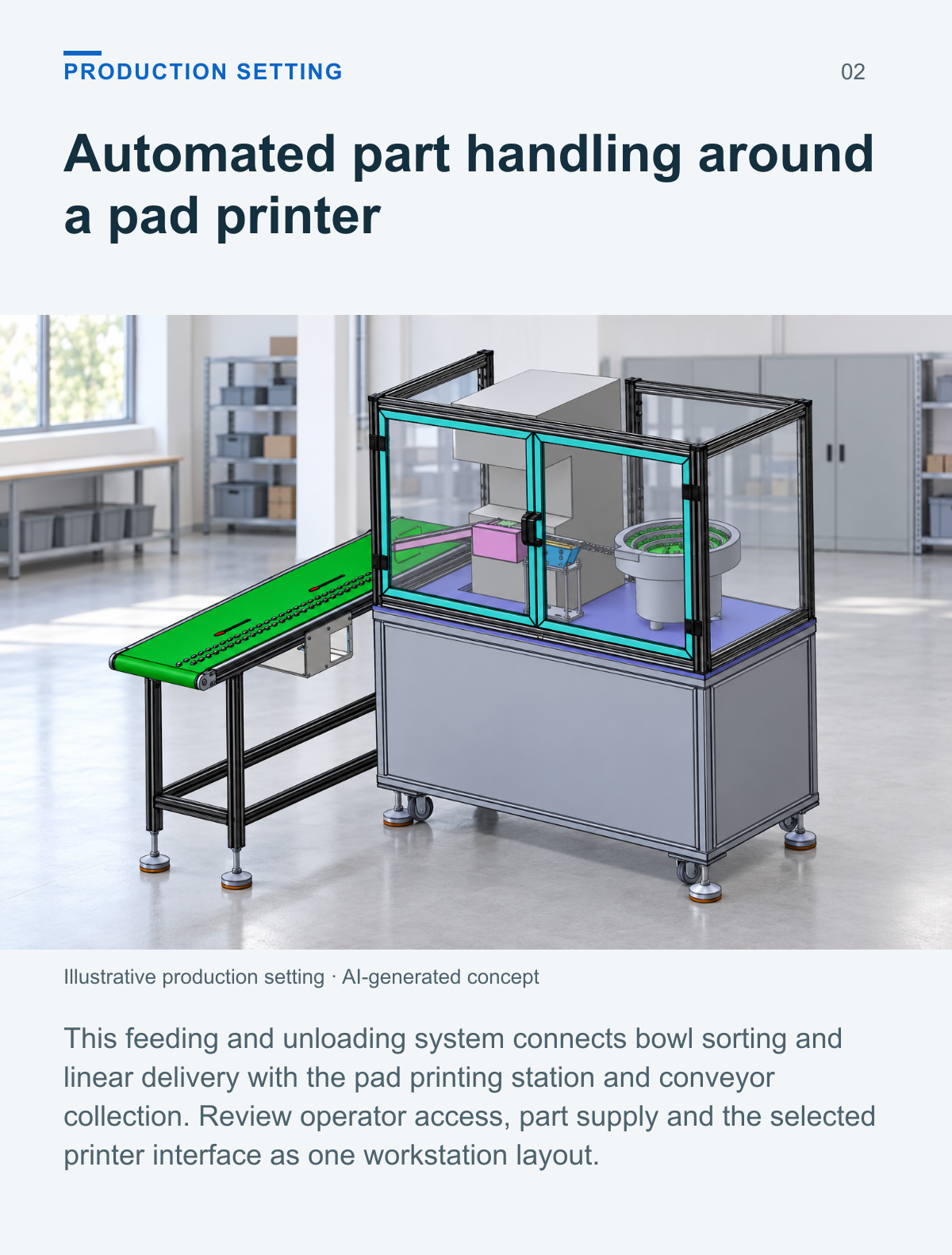
Automated part handling around a pad printer
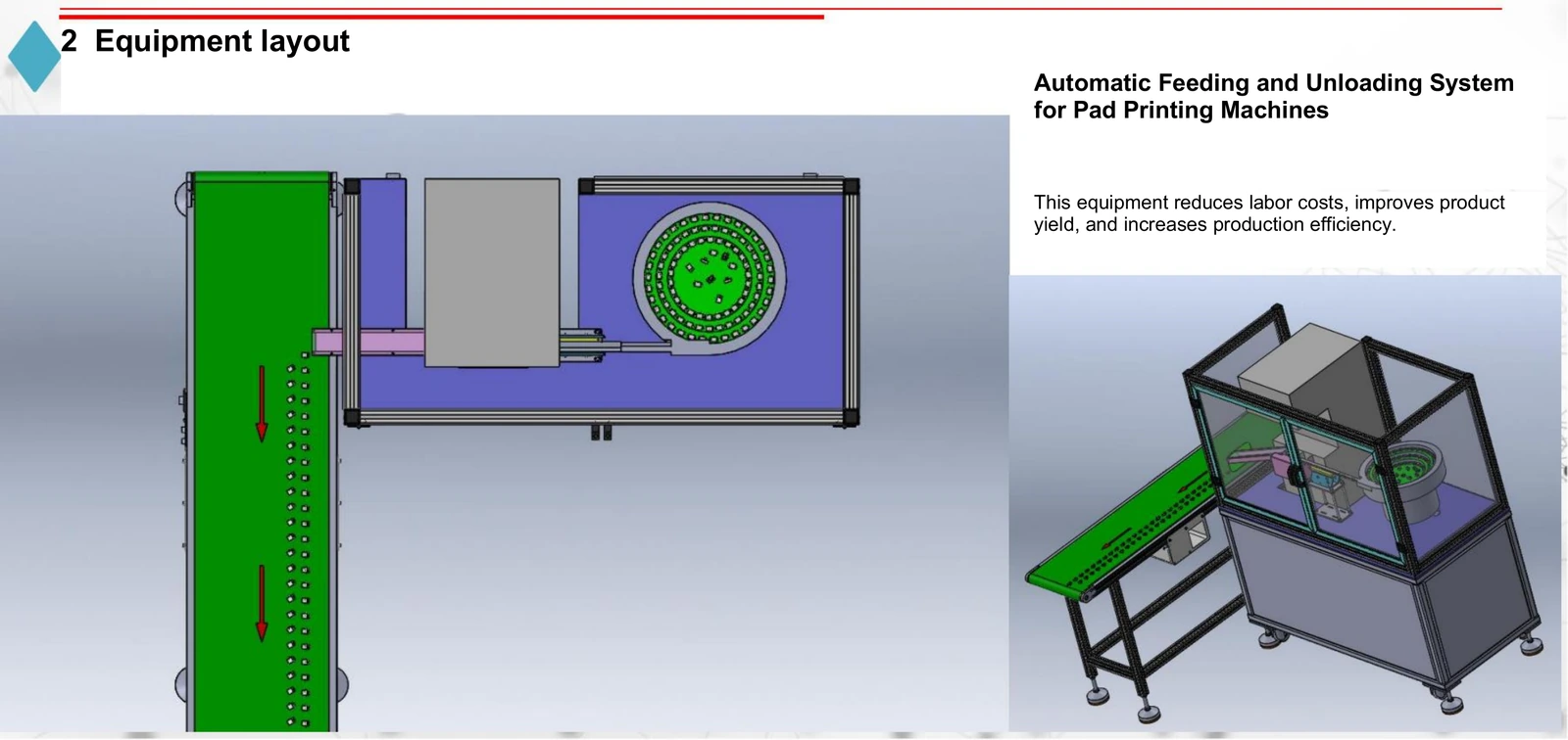
This feeding and unloading system connects bowl sorting and linear delivery with the pad printing station and conveyor collection. Review operator access, part supply and the selected printer interface as one workstation layout.
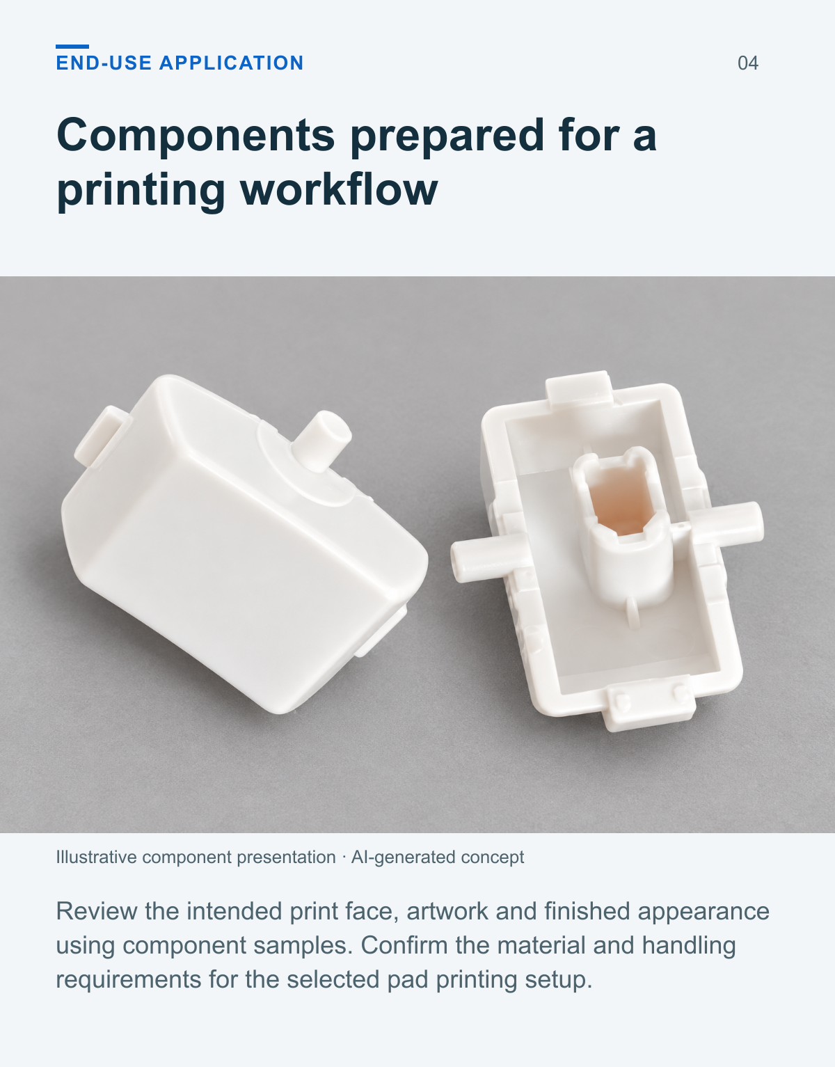
Components prepared for a printing workflow
Review the intended print face, artwork and finished appearance using component samples. Confirm the material and handling requirements for the selected pad printing setup.
Feeding positioning and unloading
Vibratory bowl feeding
The bowl uses vibration to arrange parts in sequence before linear feeding.
Linear part delivery
The linear vibratory feeder supplies the parts to the pad printing machine.
Part positioning
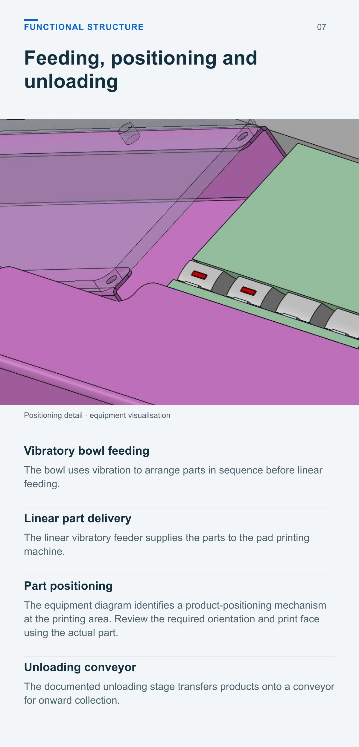
The equipment diagram identifies a product-positioning mechanism at the printing area. Review the required orientation and print face using the actual part.
Unloading conveyor
The documented unloading stage transfers products onto a conveyor for onward collection.
Review the feeding and unloading layout
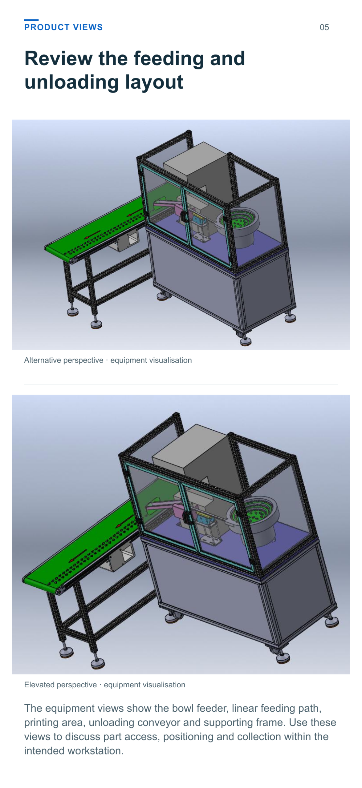
The equipment views show the bowl feeder, linear feeding path, printing area, unloading conveyor and supporting frame. Use these views to discuss part access, positioning and collection within the intended workstation.
Technical data
| Parameter | Value |
|---|---|
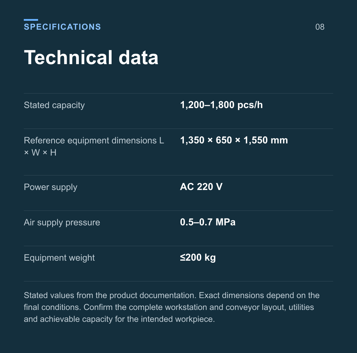
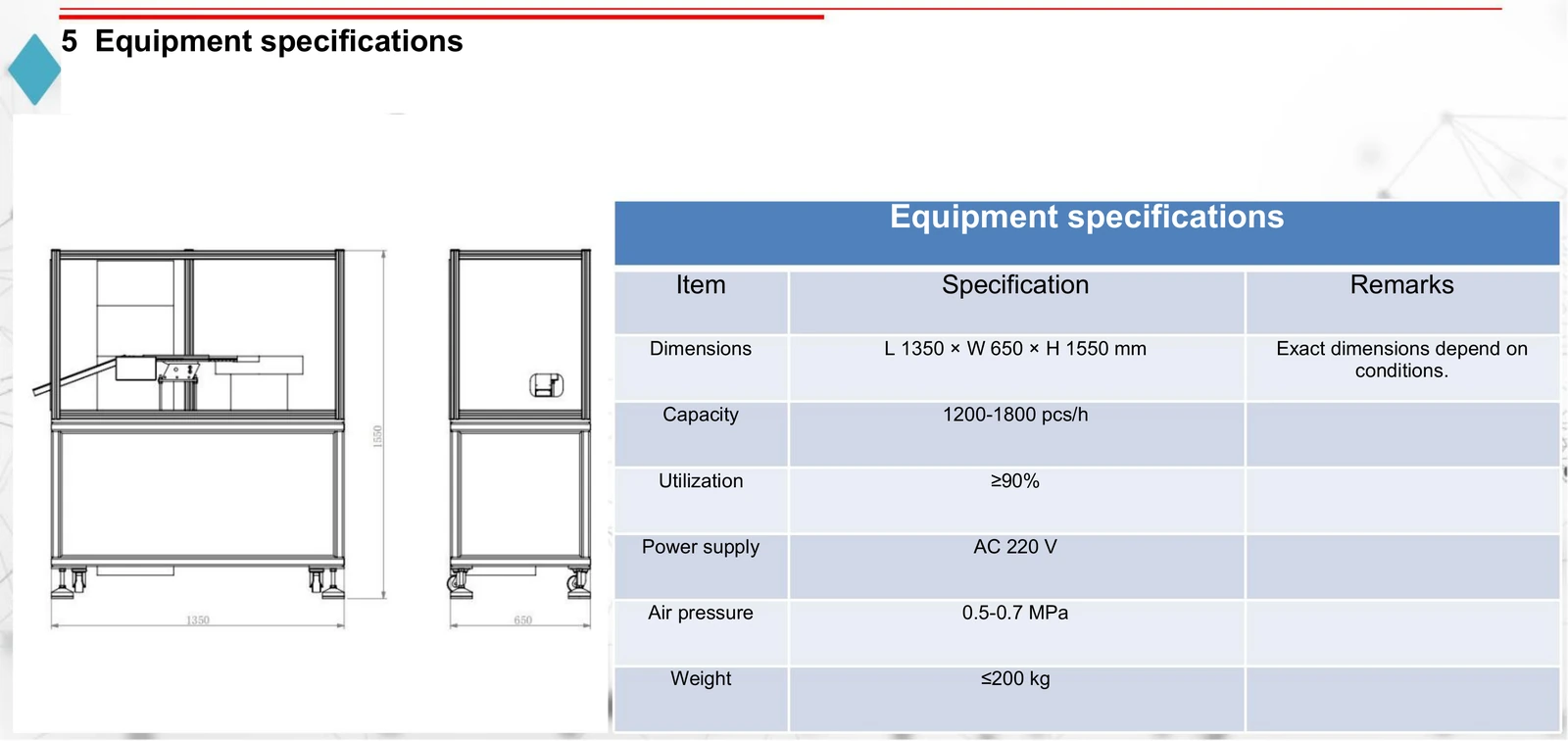
| Stated capacity | 1,200–1,800 pcs/h |
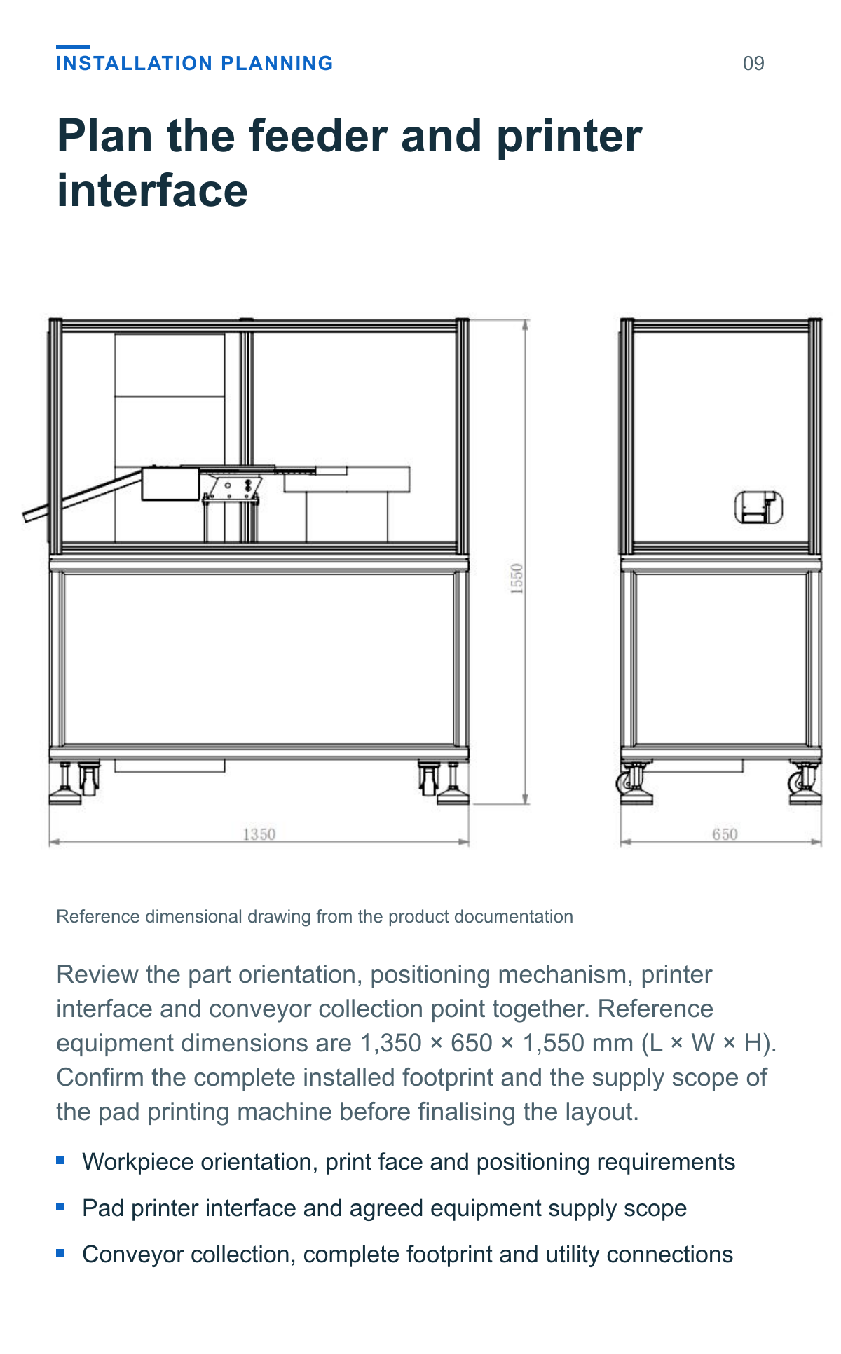
| Reference equipment dimensions L × W × H | 1,350 × 650 × 1,550 mm |
| Power supply | AC 220 V |
| Air supply pressure | 0.5–0.7 MPa |
| Equipment weight | ≤200 kg |
Stated values from the product documentation. Exact dimensions depend on the final conditions. Confirm the complete workstation and conveyor layout, utilities and achievable capacity for the intended workpiece.
Plan the feeder and printer interface
Review the part orientation, positioning mechanism, printer interface and conveyor collection point together. Reference equipment dimensions are 1,350 × 650 × 1,550 mm (L × W × H). Confirm the complete installed footprint and the supply scope of the pad printing machine before finalising the layout.
- Workpiece orientation, print face and positioning requirements
- Pad printer interface and agreed equipment supply scope
- Conveyor collection, complete footprint and utility connections
Assess the part and its presentation
Provide representative workpieces and the intended print requirements. Review how the part is oriented, presented at the print station and collected after unloading before confirming the feeding setup.
Workpiece geometry
Provide the actual component or drawing with dimensions and material details.
Orientation and print face
Identify the required orientation and the surface intended for printing.
Printer and interface
Provide the pad printer details and available interface information.
Capacity and collection
State the required hourly output and proposed conveyor collection method.
Application questions
Is the pad printing machine included
The source layout shows a pad printing machine within the workstation, but its supply scope is not specified. Confirm the printer, feeding system and unloading equipment included in the proposed setup.
Can the system handle a different component
Compatibility needs assessment with the actual component. Provide its material, dimensions, geometry, required orientation and print face so the bowl, linear feed and positioning arrangement can be reviewed.
Is the stated capacity achievable for every part
The documentation states 1,200–1,800 pcs/h. Confirm achievable capacity for the actual part, feeding behaviour and pad printing cycle before setting the production target.
What is needed for an application assessment
Provide workpiece samples or drawings, the intended print face and artwork, printer details, interface information, hourly output target and proposed collection method.
Define your pad printing feeding application
Provide the component samples, printing requirements, pad printer details and hourly production target to review the suitable feeding, positioning and unloading arrangement.
Product views and application details