PE Christmas Tree Injection Molding Robot
Single Level 2 Output
Wire insertion and take-out for moulded PE branches.
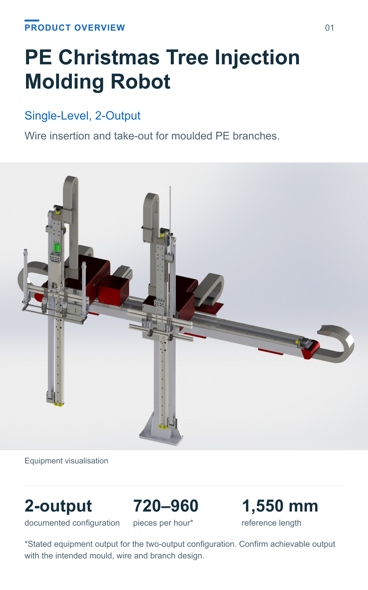
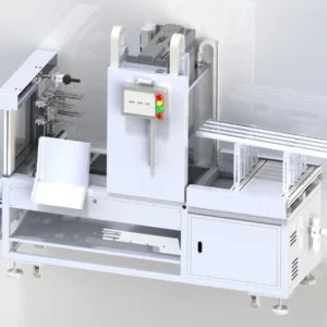
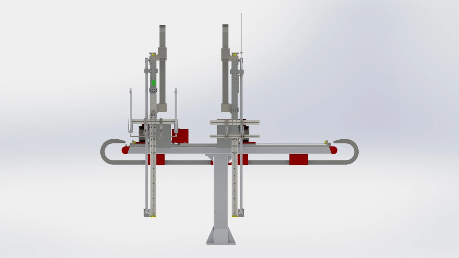
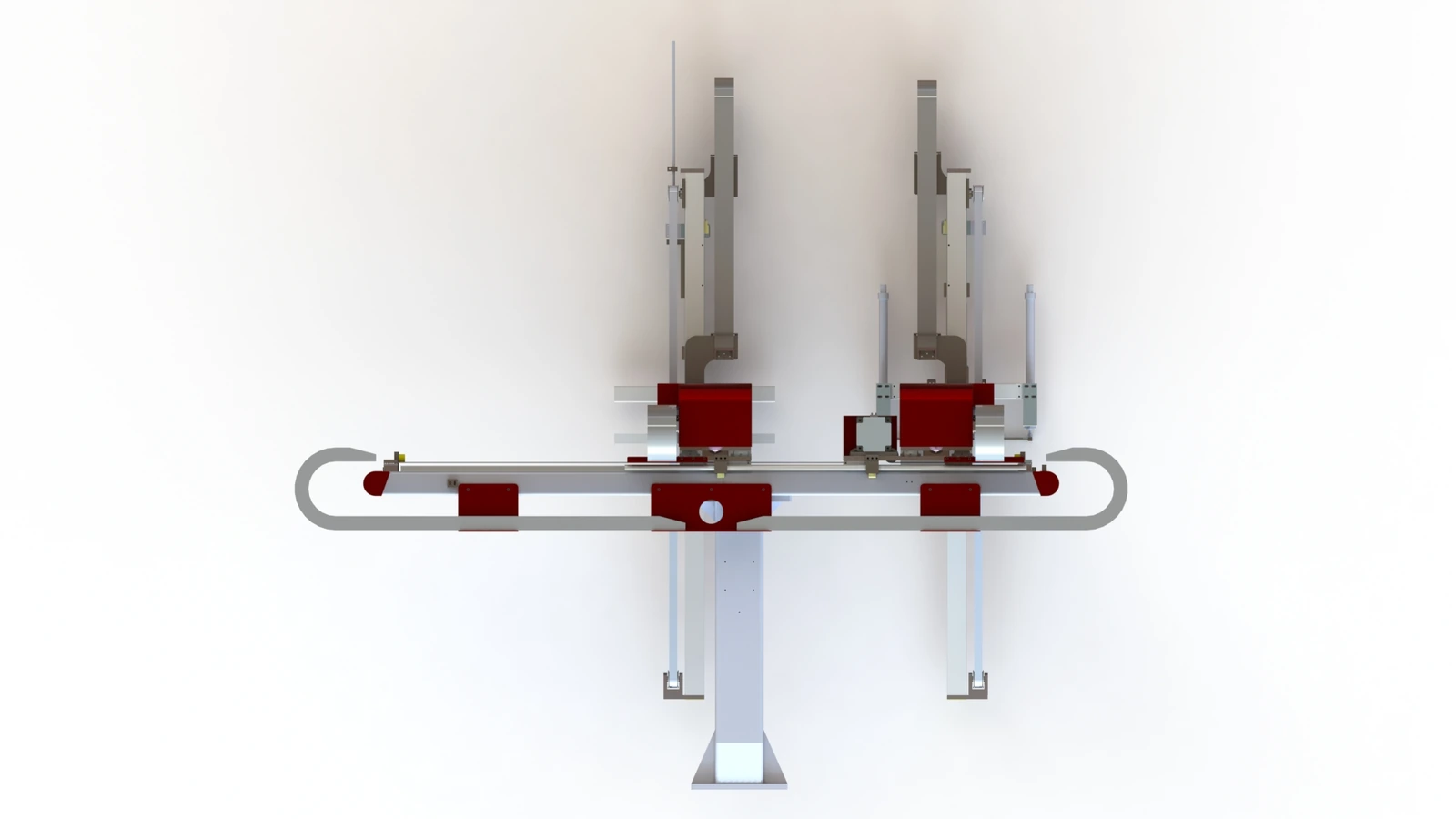
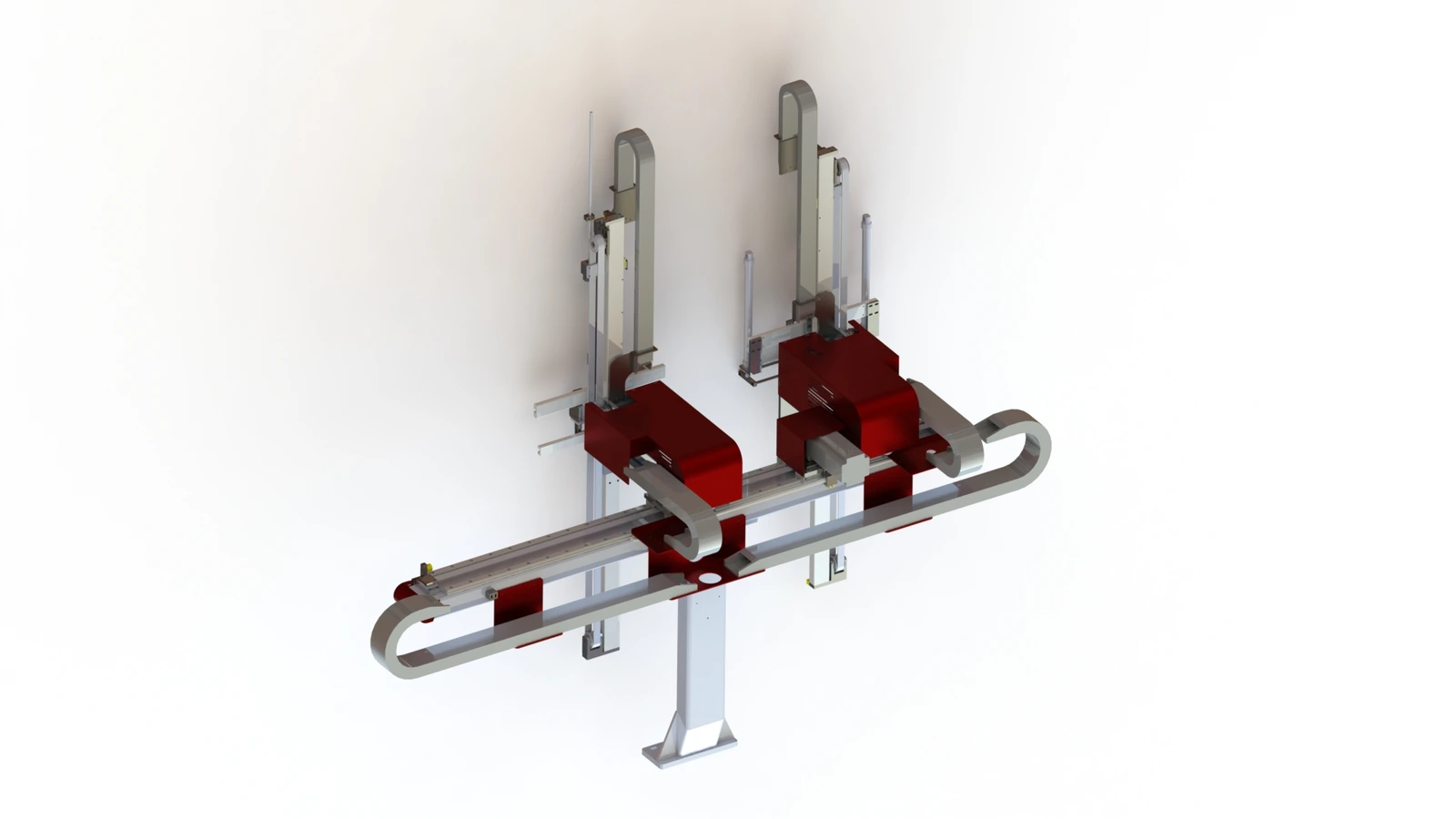
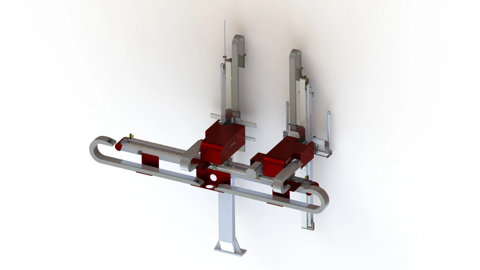
A single-level, 2-output Christmas tree injection molding robot for PE branch production. It grips wires from the wire box, inserts them into the mould holes, takes out the moulded branches and places the products after moulding.
2-output documented configuration
720–960 pieces per hour*
1,550 mm reference length
*Stated equipment output for the two-output configuration. Confirm achievable output with the intended mould, wire and branch design.
Wire insertion for PE branch moulding
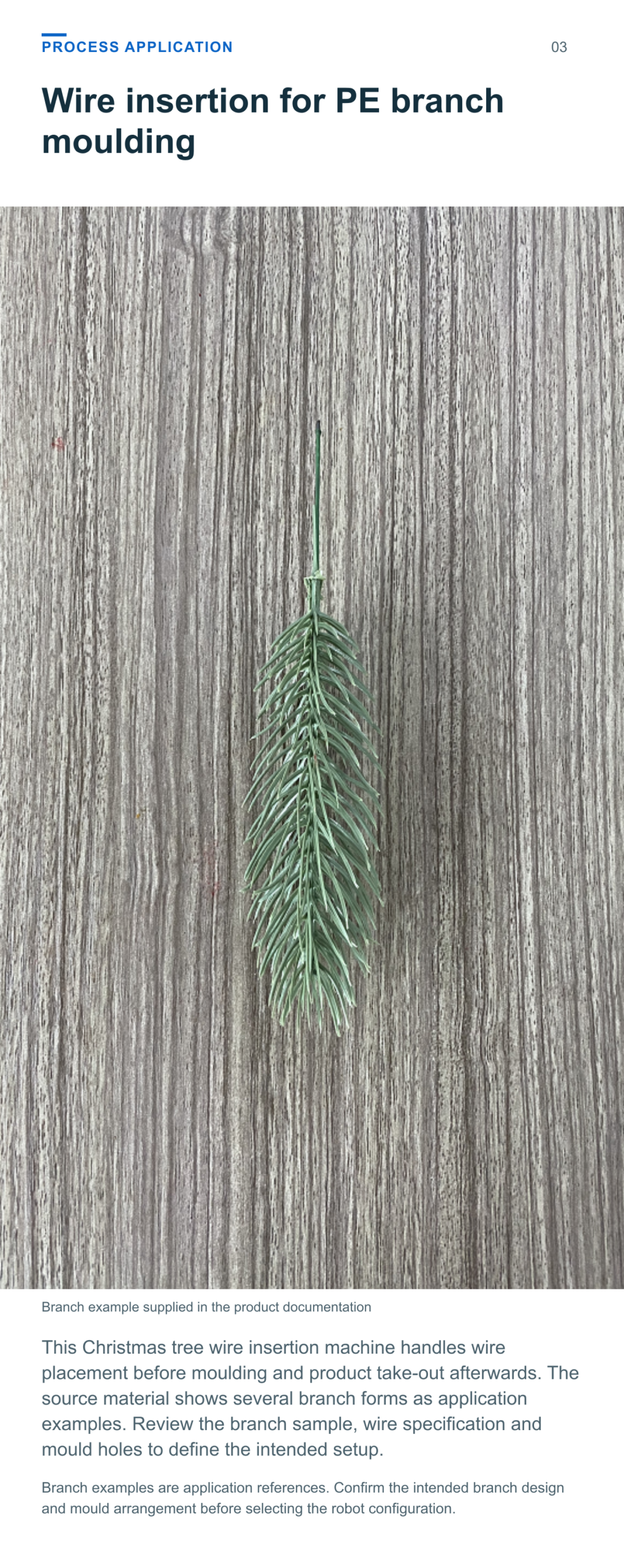
This Christmas tree wire insertion machine handles wire placement before moulding and product take-out afterwards. The source material shows several branch forms as application examples. Review the branch sample, wire specification and mould holes to define the intended setup.
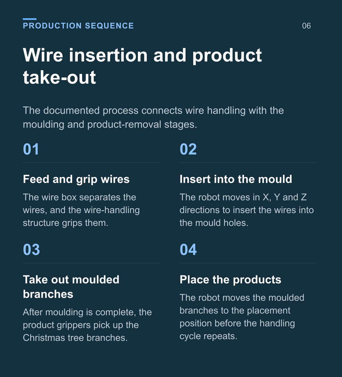
Wire insertion and product take out
The documented process connects wire handling with the moulding and product-removal stages.
Feed and grip wires The wire box separates the wires, and the wire-handling structure grips them.
Insert into the mould The robot moves in X, Y and Z directions to insert the wires into the mould holes.
Take out moulded branches After moulding is complete, the product grippers pick up the Christmas tree branches.
Place the products The robot moves the moulded branches to the placement position before the handling cycle repeats.
Wire handling at the moulding machine
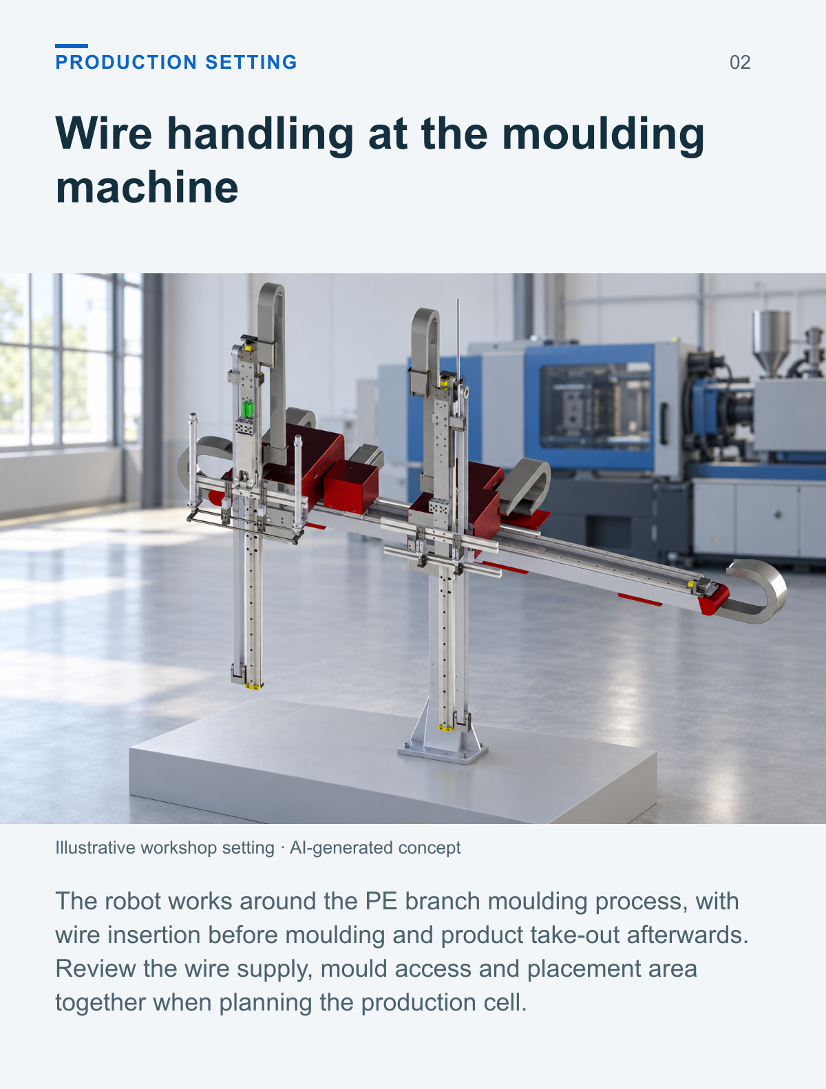
The robot works around the PE branch moulding process, with wire insertion before moulding and product take-out afterwards. Review the wire supply, mould access and placement area together when planning the production cell.
Moulded branches for artificial trees
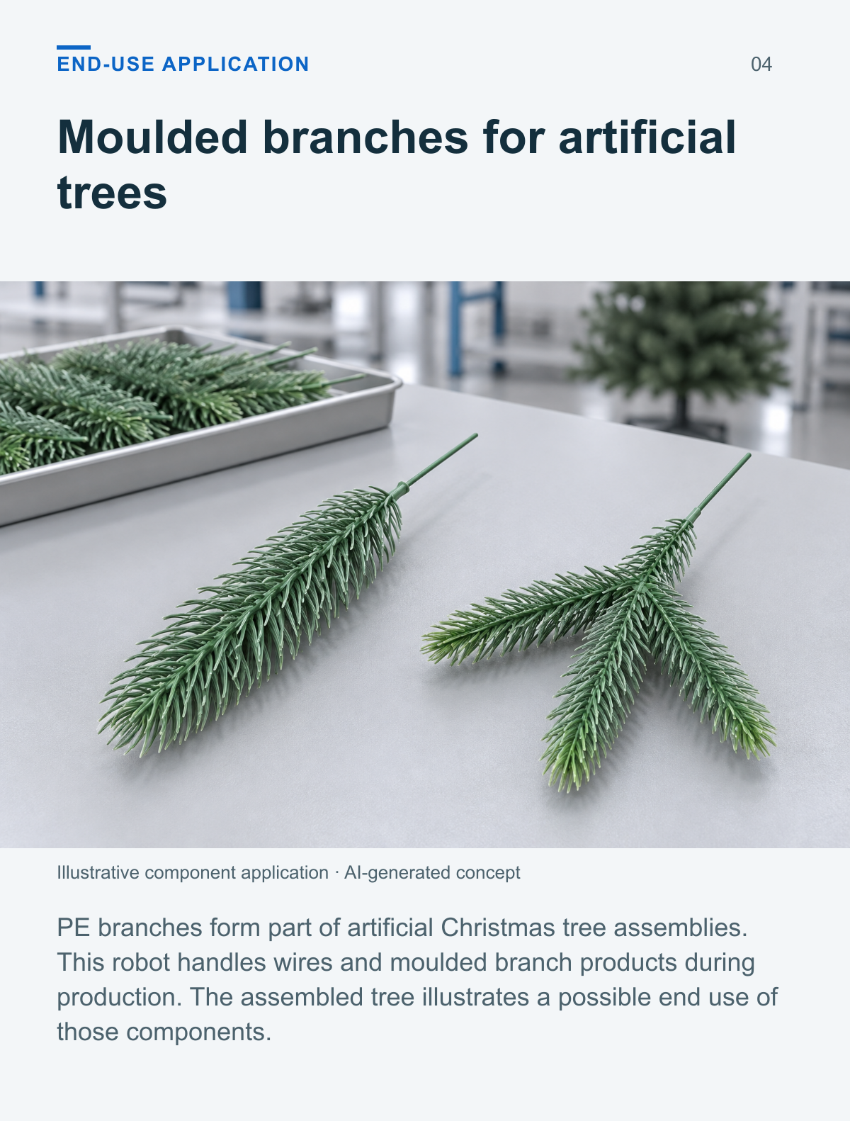
PE branches form part of artificial Christmas tree assemblies. This robot handles wires and moulded branch products during production. The assembled tree illustrates a possible end use of those components.
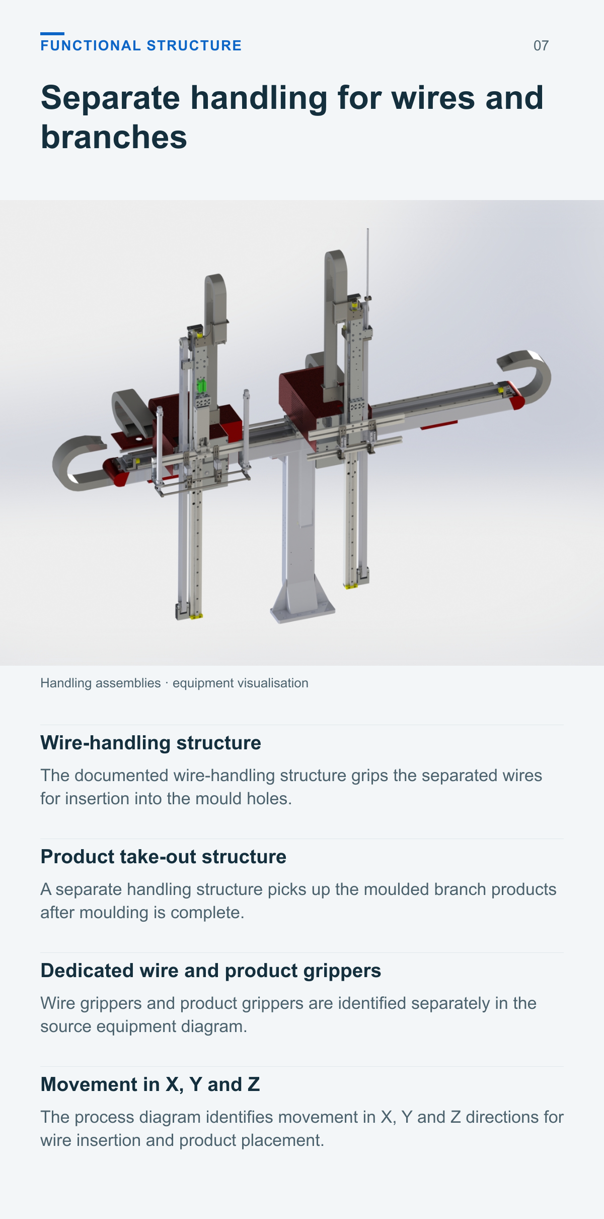
Separate handling for wires and branches
Wire handling structure
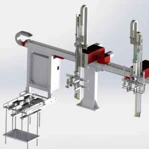
The documented wire-handling structure grips the separated wires for insertion into the mould holes.
Product take out structure
A separate handling structure picks up the moulded branch products after moulding is complete.
Dedicated wire and product grippers
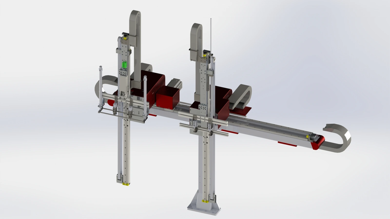
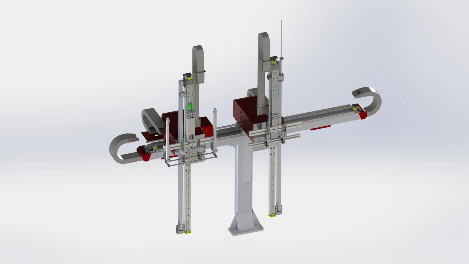
Wire grippers and product grippers are identified separately in the source equipment diagram.
Movement in X Y and Z
The process diagram identifies movement in X, Y and Z directions for wire insertion and product placement.
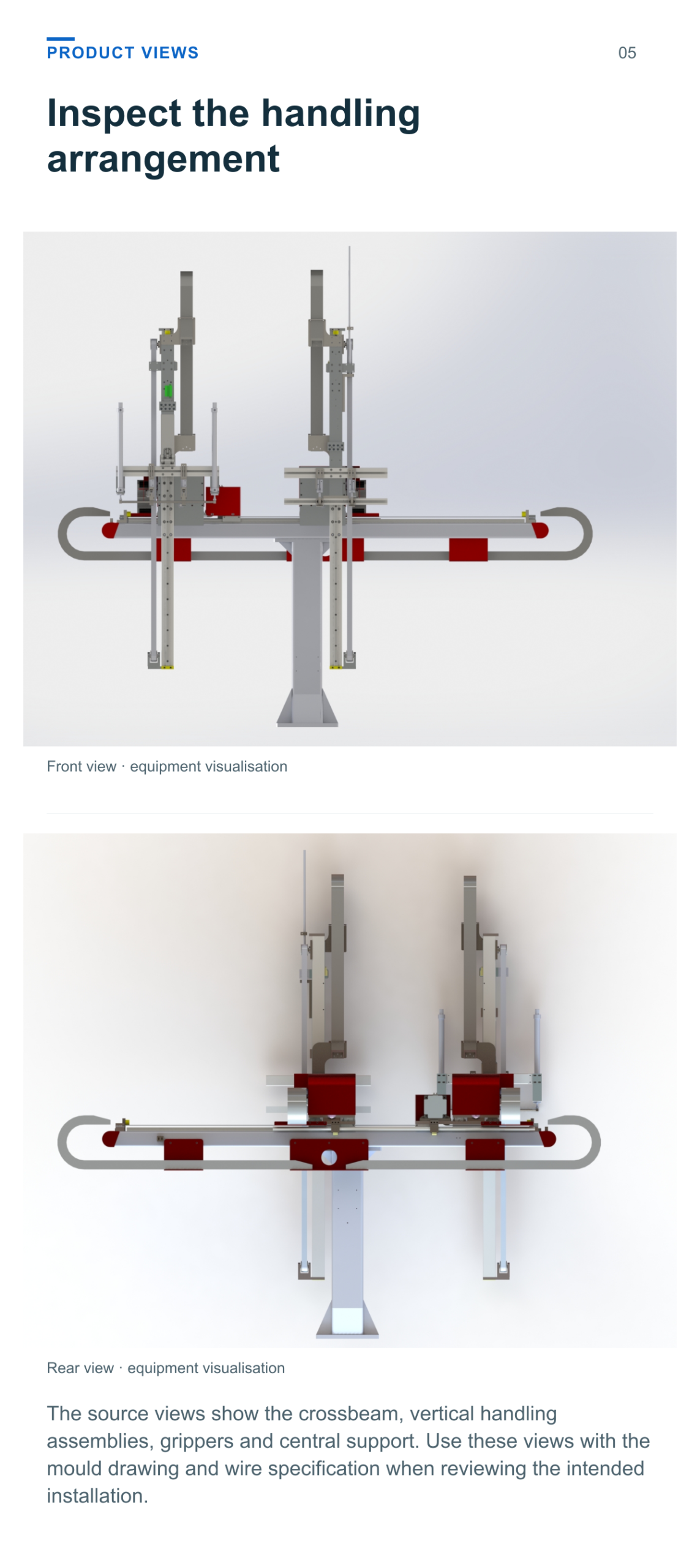
Inspect the handling arrangement
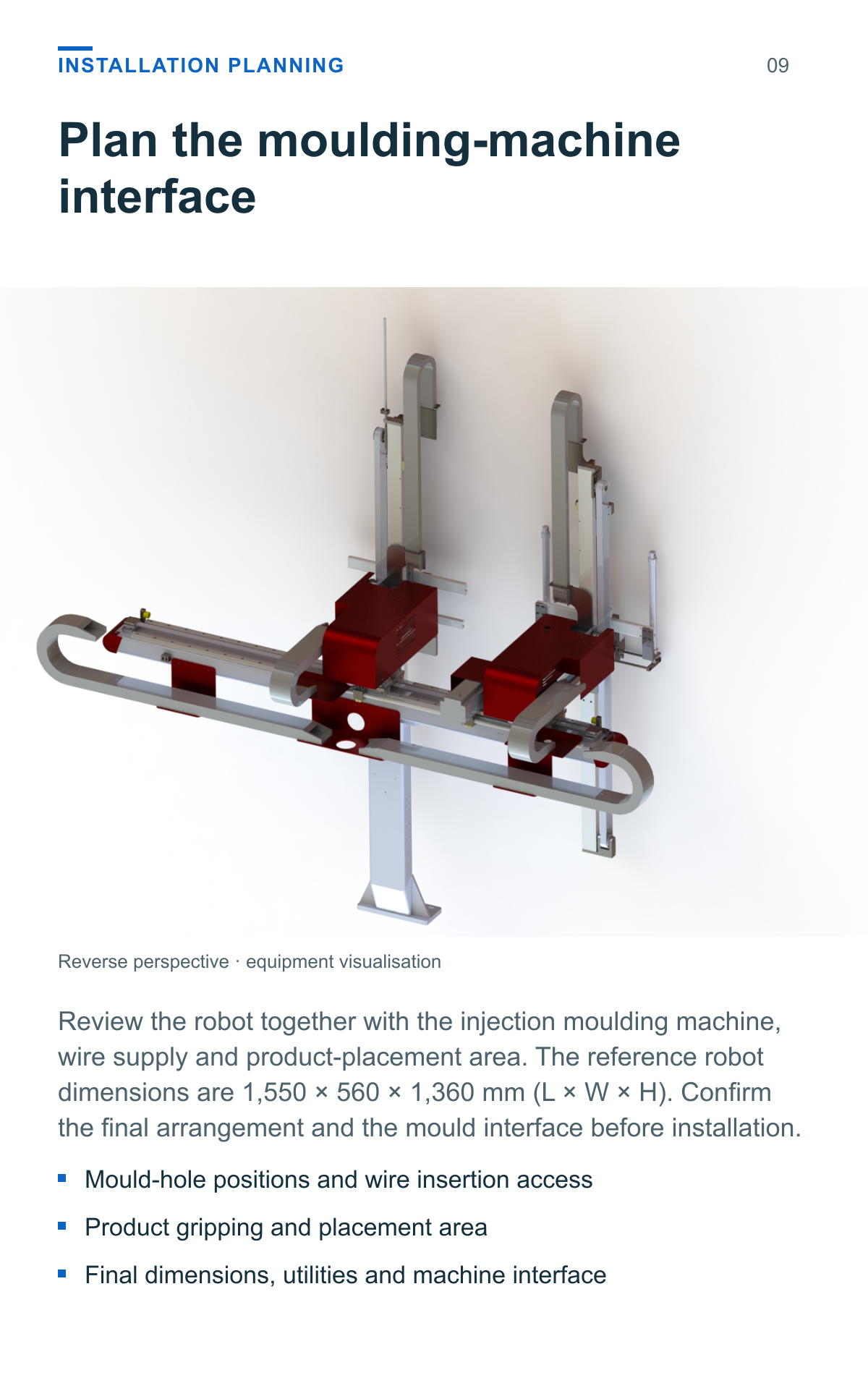
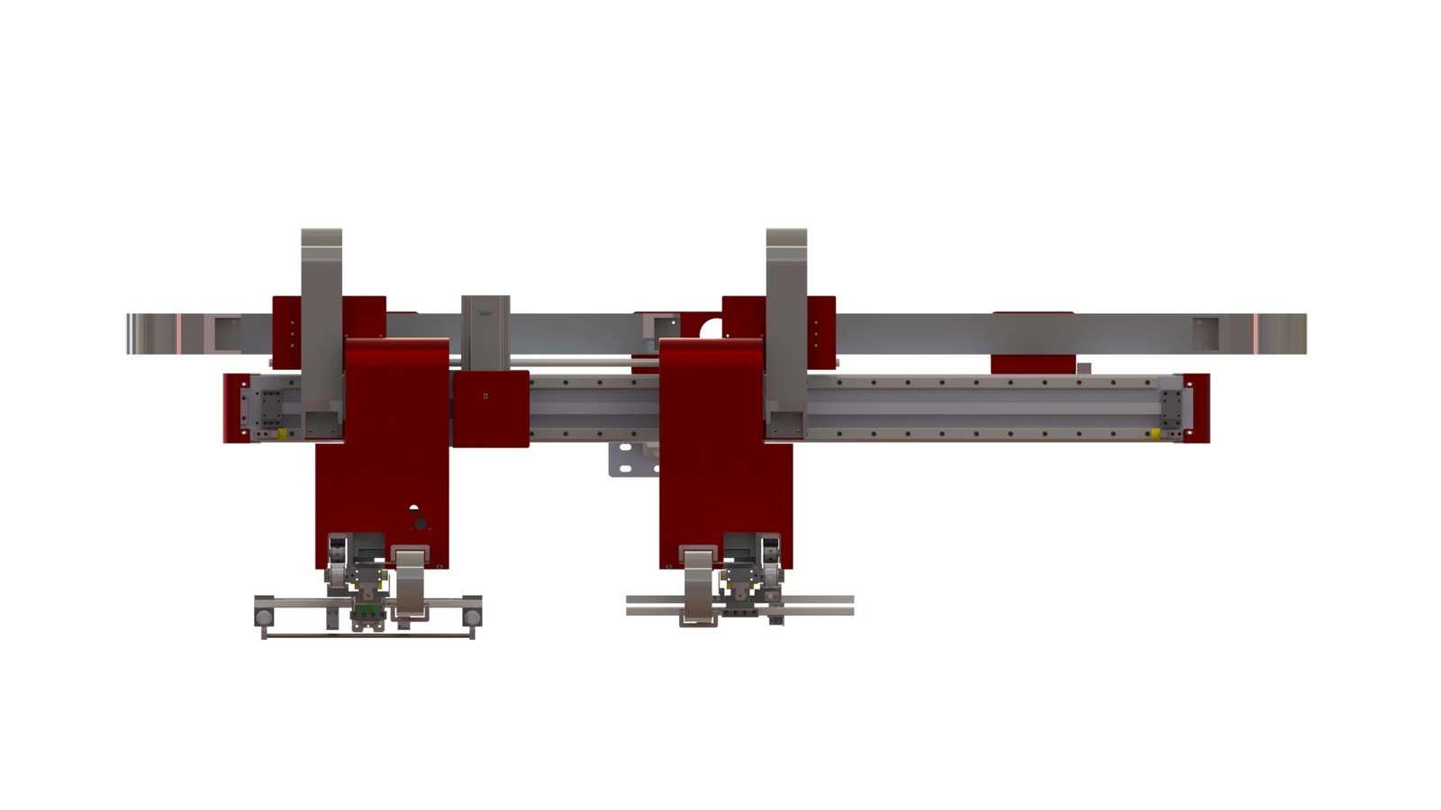
The source views show the crossbeam, vertical handling assemblies, grippers and central support. Use these views with the mould drawing and wire specification when reviewing the intended installation.
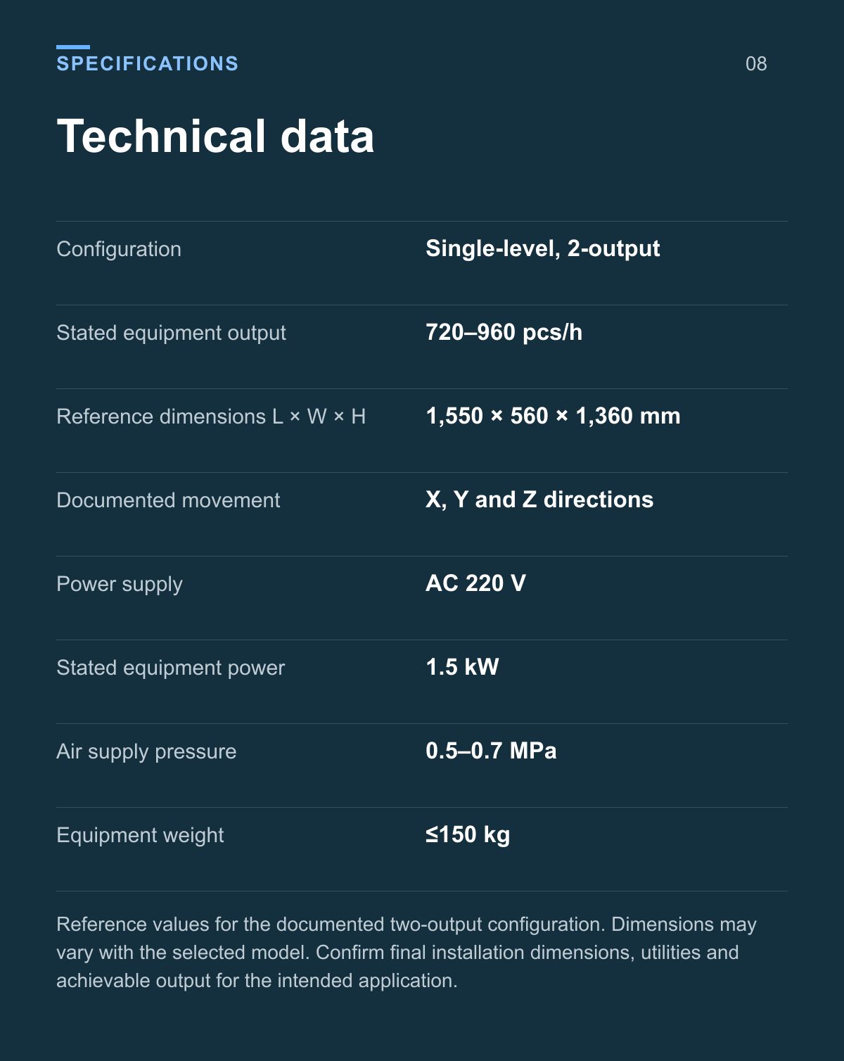
Technical data
| Parameter | Value |
|---|---|
| Configuration | Single-level, 2-output |
| Stated equipment output | 720–960 pcs/h |
| Reference dimensions L × W × H | 1,550 × 560 × 1,360 mm |
| Documented movement | X, Y and Z directions |
| Power supply | AC 220 V |
| Stated equipment power | 1.5 kW |
| Air supply pressure | 0.5–0.7 MPa |
| Equipment weight | ≤150 kg |
Reference values for the documented two-output configuration. Dimensions may vary with the selected model. Confirm final installation dimensions, utilities and achievable output for the intended application.
Plan the moulding machine interface
Review the robot together with the injection moulding machine, wire supply and product-placement area. The reference robot dimensions are 1,550 × 560 × 1,360 mm (L × W × H). Confirm the final arrangement and the mould interface before installation.
- Mould-hole positions and wire insertion access
- Product gripping and placement area
- Final dimensions, utilities and machine interface
Assess the branch wire and mould
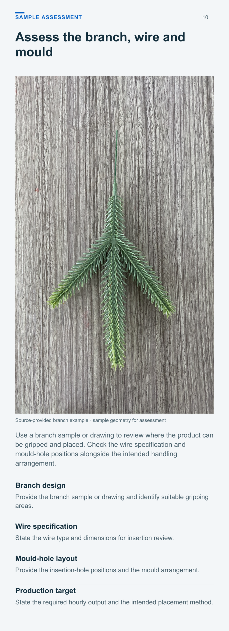
Use a branch sample or drawing to review where the product can be gripped and placed. Check the wire specification and mould-hole positions alongside the intended handling arrangement.
Branch design
Provide the branch sample or drawing and identify suitable gripping areas.
Wire specification
State the wire type and dimensions for insertion review.
Mould hole layout
Provide the insertion-hole positions and the mould arrangement.
Production target
State the required hourly output and the intended placement method.
Application questions
What does the 2 output configuration mean
The source specification describes a model producing two products at a time. Its stated equipment output is 720–960 pcs/h; this figure already applies to the two-output configuration.
Which operations does the robot handle
The documented process covers wire pickup, insertion into mould holes, take-out of moulded branches and product placement. Confirm the required timing with the intended moulding machine.
How is a branch design assessed
Provide the branch sample or drawing, wire specification and mould-hole layout. These define the application review for wire insertion, gripping and product placement.
Does this product include the injection moulding machine
This product is the wire-insertion and take-out robot. Review the injection moulding machine separately and confirm the machine interface and final scope of supply.
Define your two output branch setup
Provide branch samples or drawings, wire details, the mould-hole layout, required hourly output and information about the injection moulding machine to review the suitable robot configuration.
Product views and application details