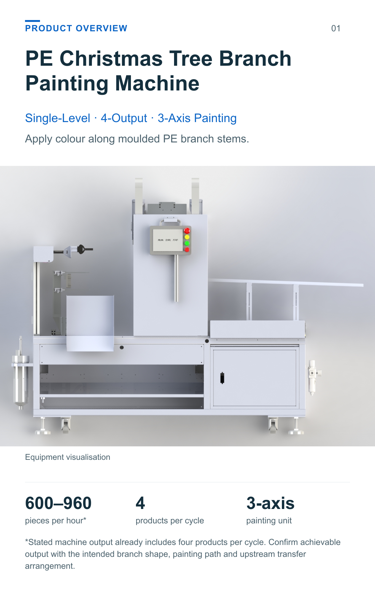
PE Christmas Tree Branch Painting Machine
Single Level 4 Output 3 Axis Painting
Apply colour along moulded PE branch stems.
This single-level, 4-output yellow core painting machine receives moulded PE branches from an upstream robot, positions them for centre-stem painting and places the painted branches on a product rack.
600–960 pieces per hour*
4 products per cycle
3-axis painting unit
*Stated machine output already includes four products per cycle. Confirm achievable output with the intended branch shape, painting path and upstream transfer arrangement.
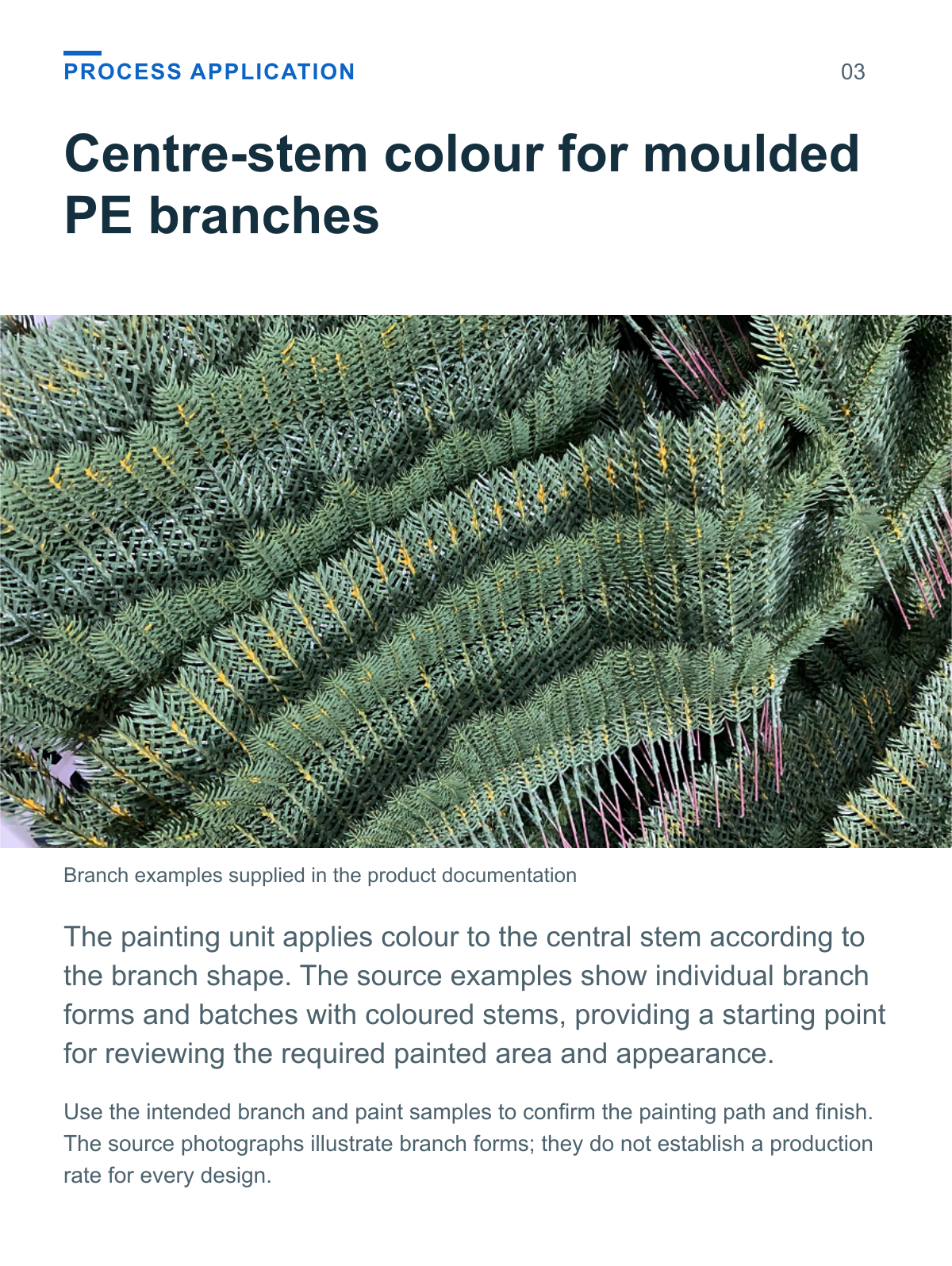
Centre stem colour for moulded PE branches
The painting unit applies colour to the central stem according to the branch shape. The source examples show individual branch forms and batches with coloured stems, providing a starting point for reviewing the required painted area and appearance.
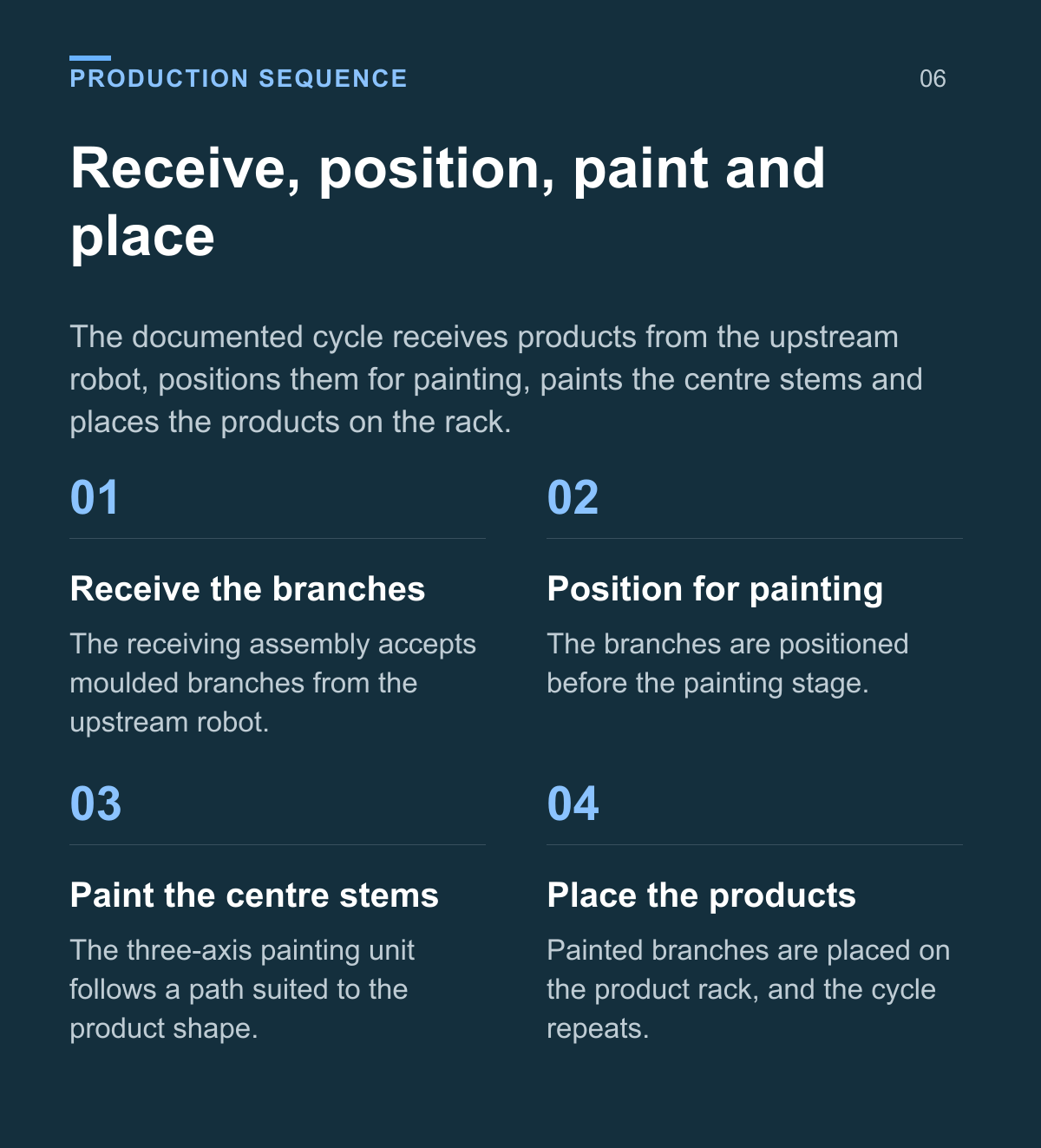
Receive position paint and place
The documented cycle receives products from the upstream robot, positions them for painting, paints the centre stems and places the products on the rack.
Receive the branches The receiving assembly accepts moulded branches from the upstream robot.
Position for painting The branches are positioned before the painting stage.
Paint the centre stems The three-axis painting unit follows a path suited to the product shape.
Place the products Painted branches are placed on the product rack, and the cycle repeats.
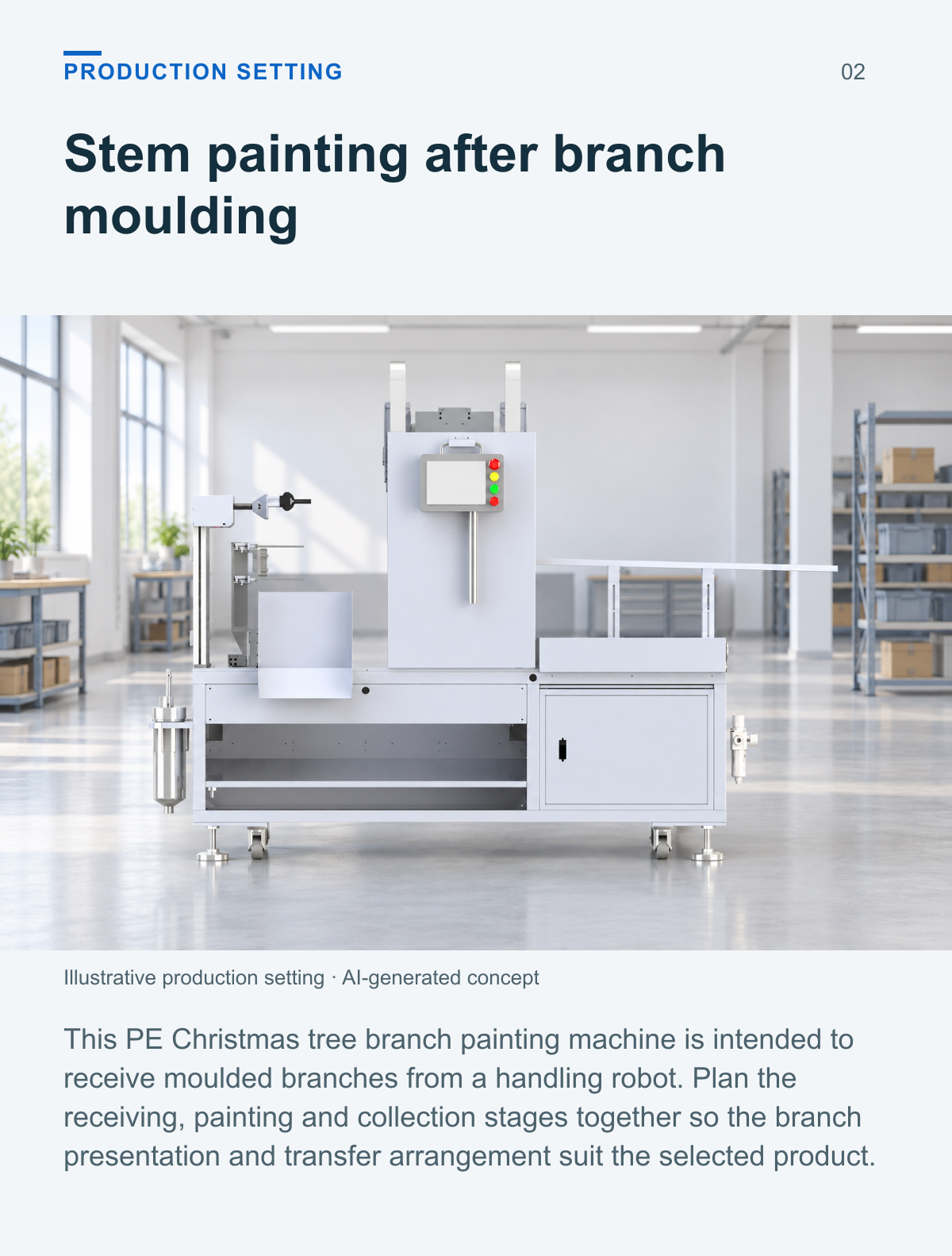
Stem painting after branch moulding
This PE Christmas tree branch painting machine is intended to receive moulded branches from a handling robot. Plan the receiving, painting and collection stages together so the branch presentation and transfer arrangement suit the selected product.
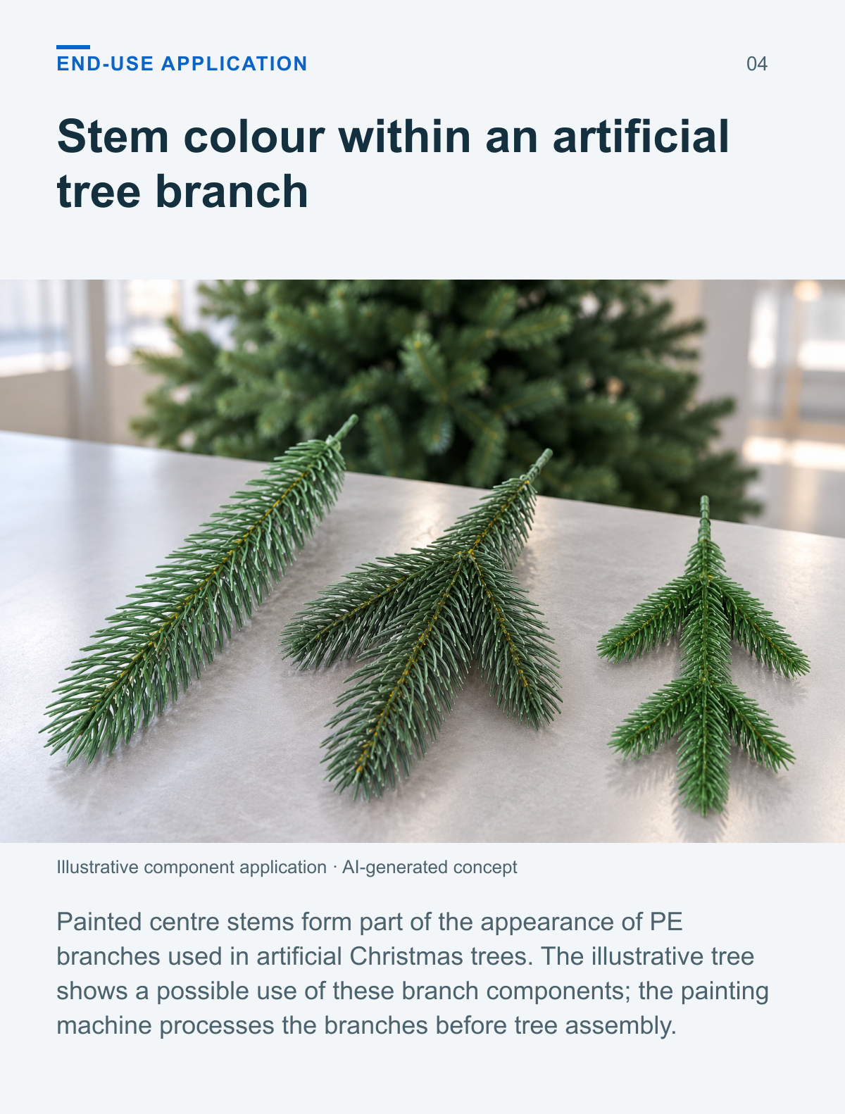
Stem colour within an artificial tree branch
Painted centre stems form part of the appearance of PE branches used in artificial Christmas trees. The illustrative tree shows a possible use of these branch components; the painting machine processes the branches before tree assembly.
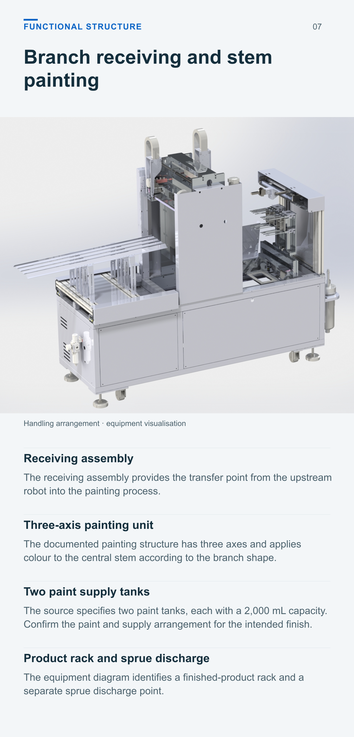
Branch receiving and stem painting
Receiving assembly
The receiving assembly provides the transfer point from the upstream robot into the painting process.
Three axis painting unit
The documented painting structure has three axes and applies colour to the central stem according to the branch shape.
Two paint supply tanks
The source specifies two paint tanks, each with a 2,000 mL capacity. Confirm the paint and supply arrangement for the intended finish.
Product rack and sprue discharge
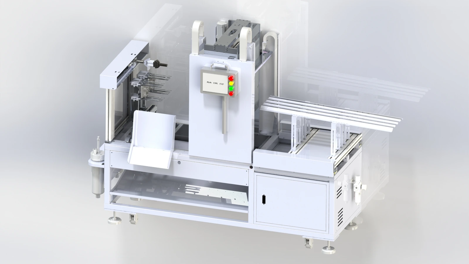
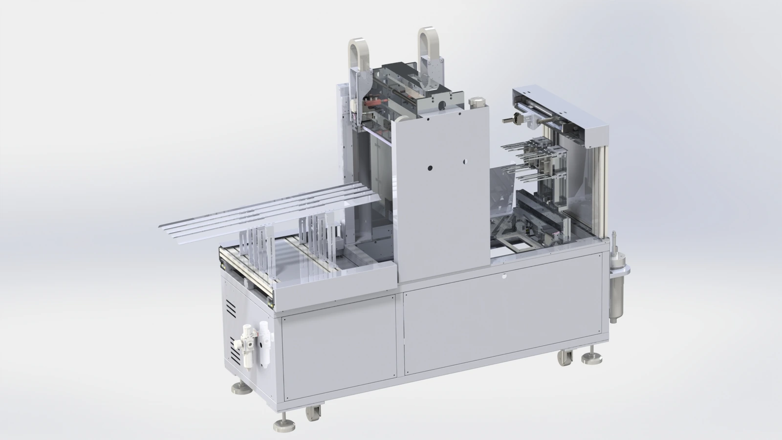
The equipment diagram identifies a finished-product rack and a separate sprue discharge point.
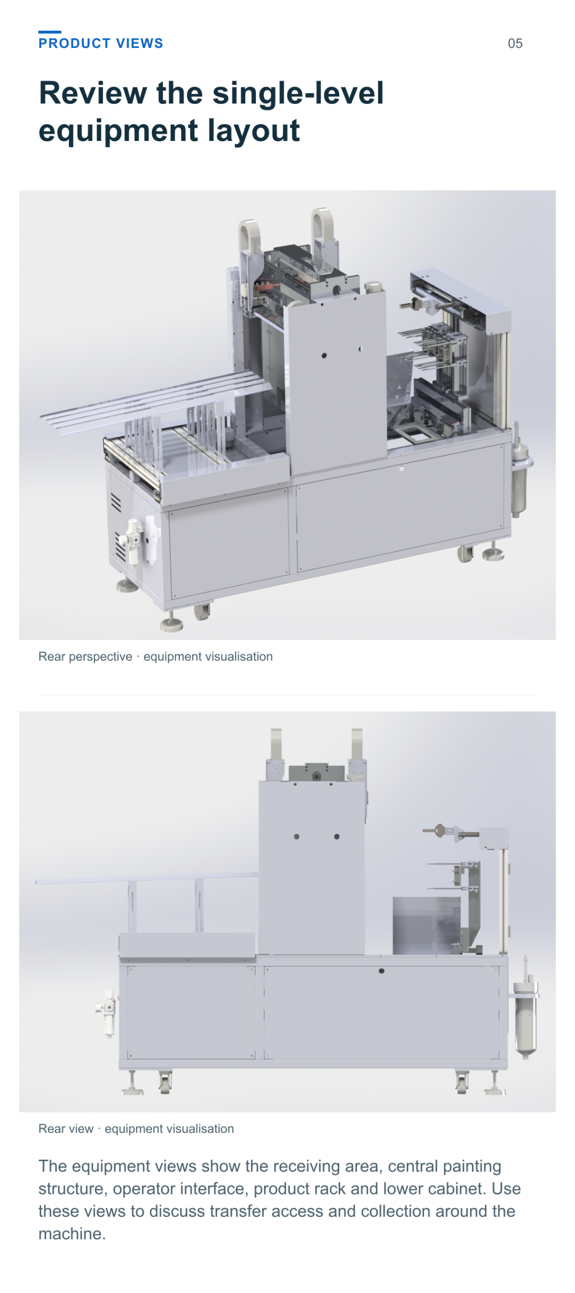
Review the single level equipment layout
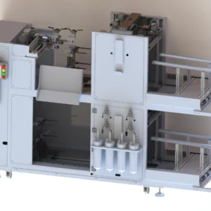
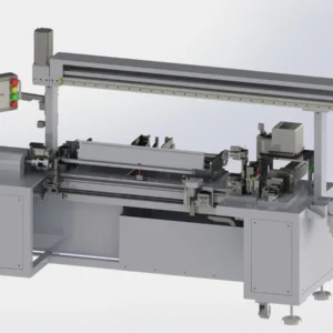
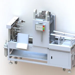
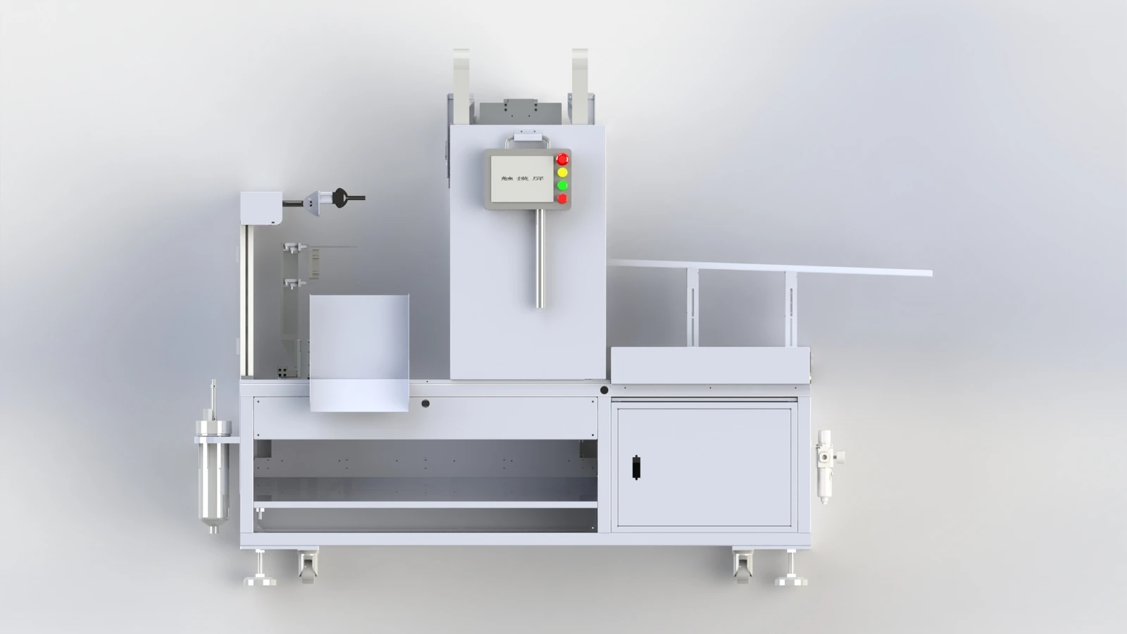
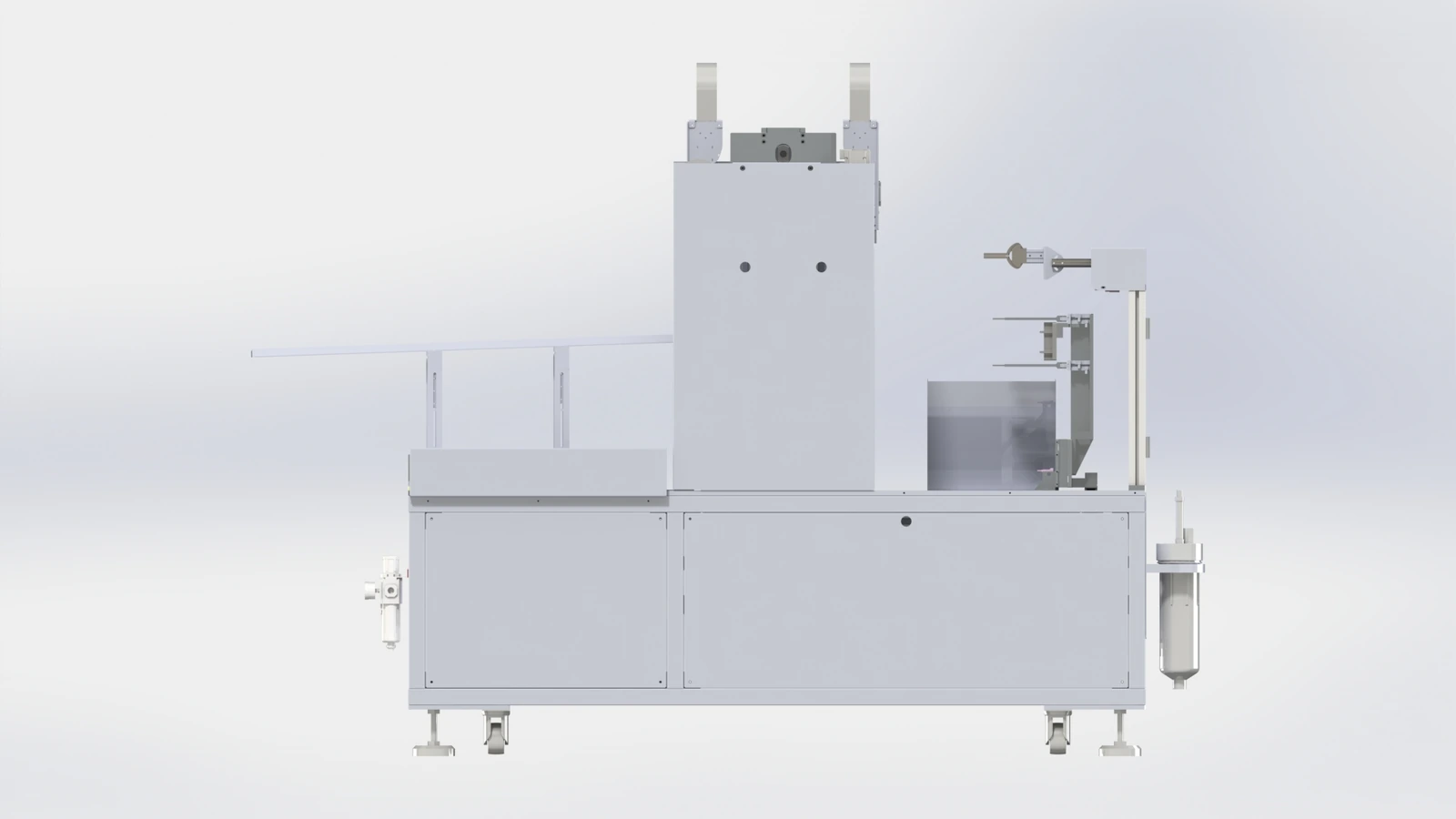
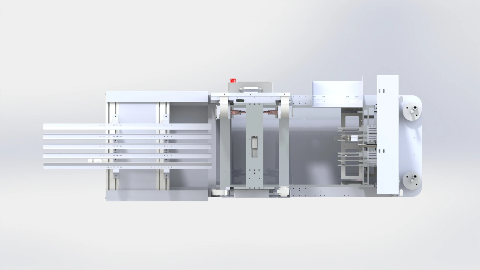
The equipment views show the receiving area, central painting structure, operator interface, product rack and lower cabinet. Use these views to discuss transfer access and collection around the machine.
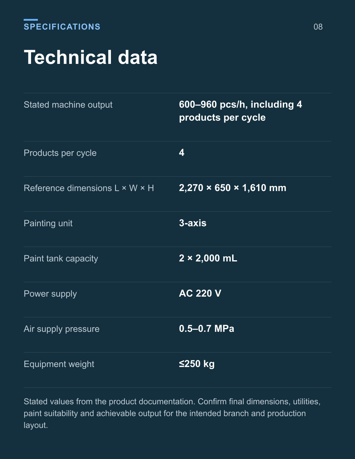
Technical data
| Parameter | Value |
|---|---|
| Stated machine output | 600–960 pcs/h, including 4 products per cycle |
| Products per cycle | 4 |
| Reference dimensions L × W × H | 2,270 × 650 × 1,610 mm |
| Painting unit | 3-axis |
| Paint tank capacity | 2 × 2,000 mL |
| Power supply | AC 220 V |
| Air supply pressure | 0.5–0.7 MPa |
| Equipment weight | ≤250 kg |
Stated values from the product documentation. Confirm final dimensions, utilities, paint suitability and achievable output for the intended branch and production layout.
Plan the robot to painting transfer
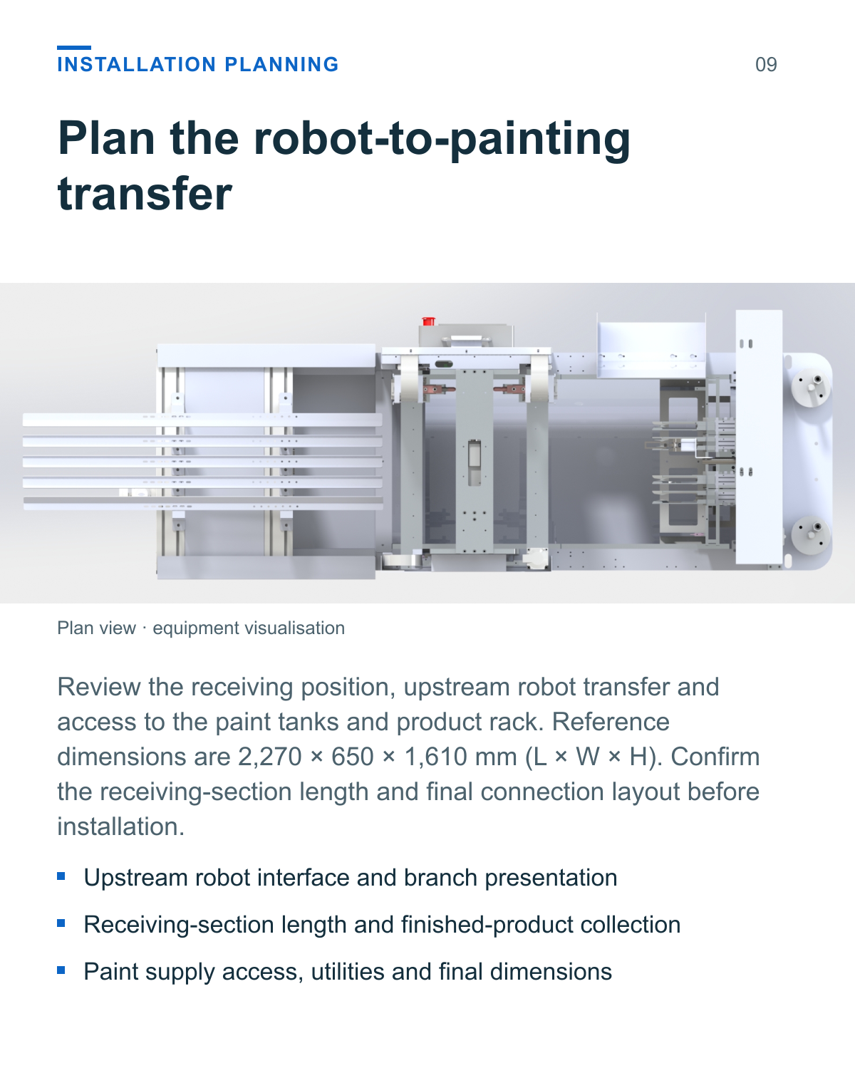
Review the receiving position, upstream robot transfer and access to the paint tanks and product rack. Reference dimensions are 2,270 × 650 × 1,610 mm (L × W × H). Confirm the receiving-section length and final connection layout before installation.
- Upstream robot interface and branch presentation
- Receiving-section length and finished-product collection
- Paint supply access, utilities and final dimensions
Assess the branch and painting path
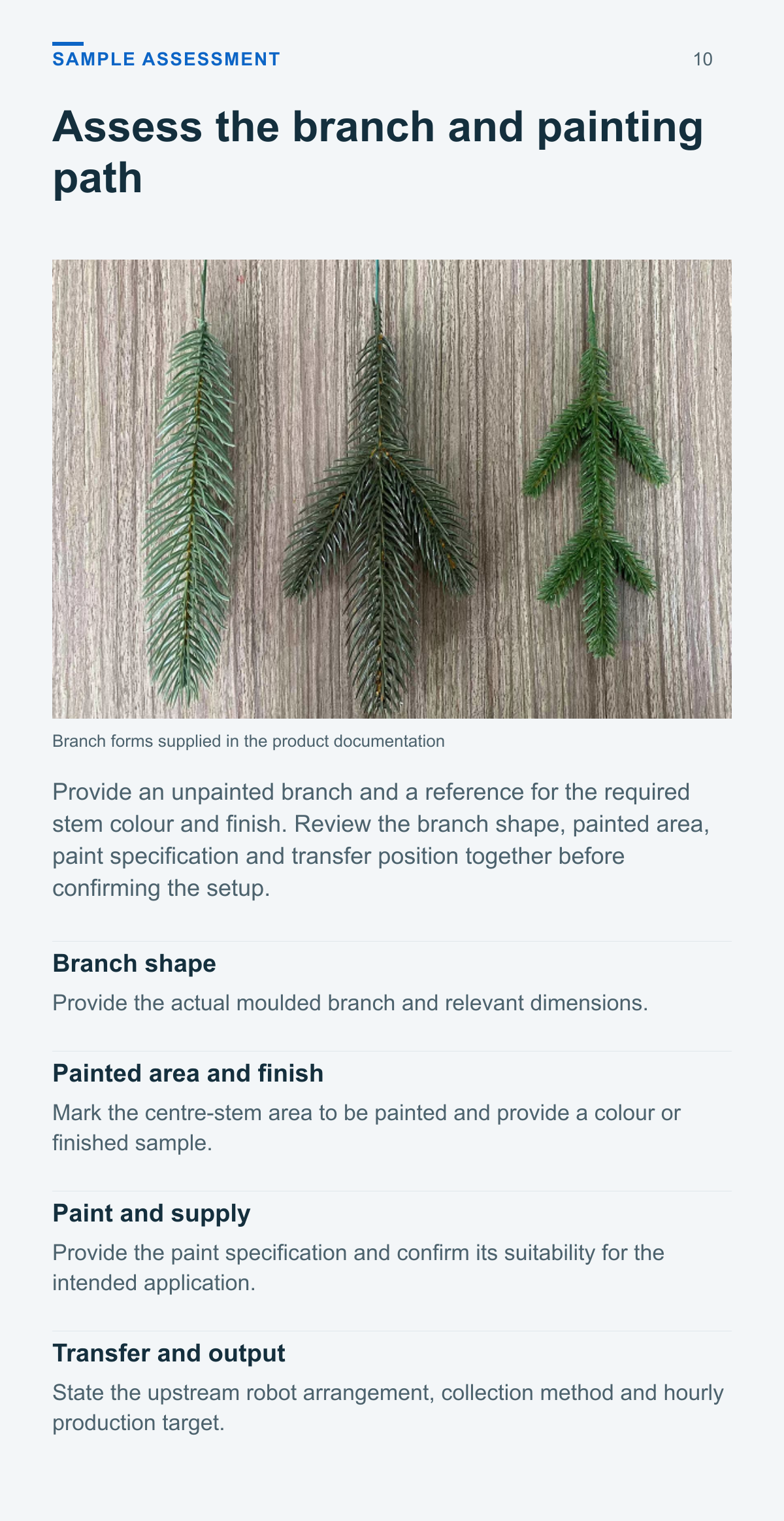
Provide an unpainted branch and a reference for the required stem colour and finish. Review the branch shape, painted area, paint specification and transfer position together before confirming the setup.
Branch shape
Provide the actual moulded branch and relevant dimensions.
Painted area and finish
Mark the centre-stem area to be painted and provide a colour or finished sample.
Paint and supply
Provide the paint specification and confirm its suitability for the intended application.
Transfer and output
State the upstream robot arrangement, collection method and hourly production target.
Application questions
What does 4 output mean for capacity
The source states four products per cycle and a machine output of 600–960 pcs/h. This hourly range already includes the four-output configuration; it is not multiplied by four.
Which part of the branch is painted
The documented function is to paint the central stem according to the branch shape. Review the desired painted area and finish using the actual branch sample.
Do the two tanks mean two colours at once
The documentation specifies two 2,000 mL paint supply tanks. It does not establish simultaneous two-colour operation. Confirm the supply arrangement for the intended paint and colour requirement.
What is needed to review the upstream connection
Provide branch samples, the robot transfer position, the required hourly output and the planned collection method. Confirm the receiving-section layout and painting requirements together.
Define your branch painting application
Provide the branch samples, target stem colour, paint details, upstream robot arrangement and hourly output target to review the suitable single-level painting setup.
Product views and application details