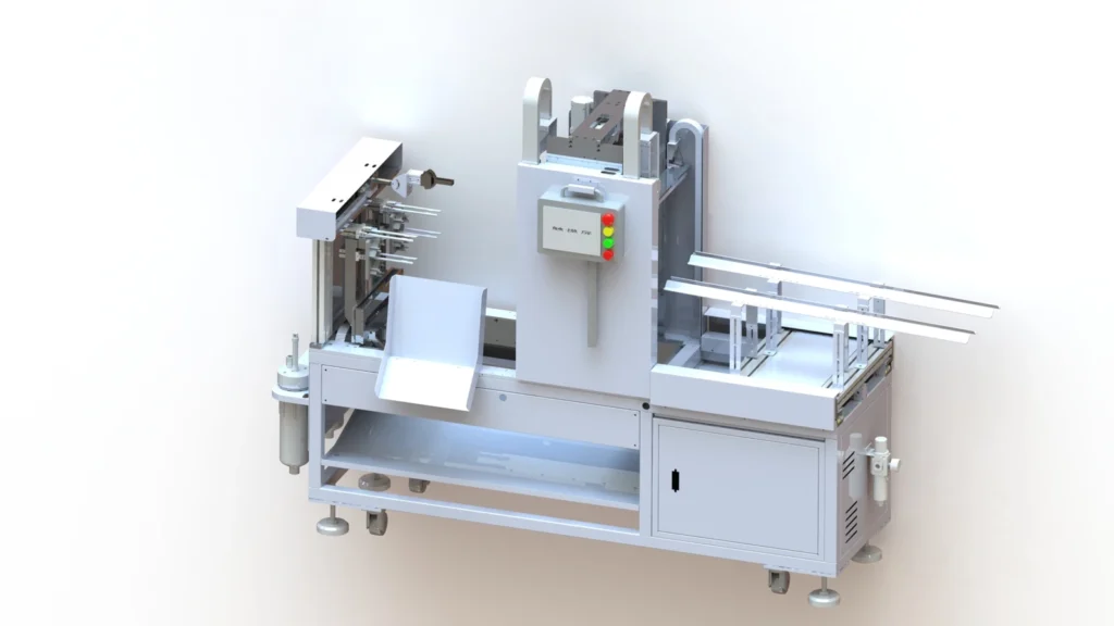
A yellow core painting machine adds color along the central stem of a molded PE Christmas tree branch. The documented method uses a needle to apply paint along that stem, following the branch shape. This is a dedicated branch-finishing stage after molding, with the colored area defined by the intended product appearance.
The name “yellow core” describes the equipment category. The supplied product information confirms that brown and other colors can also be used. A branch sample and a reference for the desired color are therefore more useful starting points than assuming every branch requires a yellow stem.
Receive, position, paint and place
The documented working sequence has four stages. First, the painting machine receives molded branches from the paired handling robot. It then positions the branches for painting. The painting structure applies paint along the central stem according to the product shape, and the painted branches are transferred to the receiving rack. The sequence then repeats.
Positioning and the painting path are reviewed together. The actual branch geometry determines the stem area that needs to be reached, while the incoming transfer arrangement determines how the branch is presented to the machine. Marking the required painted area on a sample helps make those requirements clear.
Define the color and finish
For a brown stem or another required color, provide a finished reference or a color sample together with an unpainted branch. Identify where the color should start and finish along the central stem. This keeps the discussion focused on the intended appearance of the individual PE branch.
The paint specification also needs review. The available information supports needle-applied stem painting and the use of colors beyond yellow, but does not establish a universal paint formulation or a color-change procedure. Agree the paint suitability, supply arrangement and required finish for the intended application.
Choose the corresponding machine layout
The Single-Level, 2-Output Painting Machine pairs with the corresponding single-level, two-output injection molding robot. The Single-Level, 4-Output Painting Machine pairs with the single-level, four-output robot. The Dual-Level, 4-Output Painting Machine uses upper and lower receiving, painting and collection areas and pairs with the dual-level, four-output robot.
Select the layout with the branch transfer and collection arrangement in mind. Check the receiving positions, access to the paint supply and space around the product racks. Paint-tank count describes the supply hardware; it does not by itself establish how many colors can be applied simultaneously.
Use the branch sample to guide the review
A useful application brief brings together the unpainted branch, desired stem color, marked painting area, paint details and upstream robot arrangement. Include the required hourly output and how the painted branches will be collected. These details help define the receiving, positioning, painting and placement requirements without relying on the equipment name alone.
Review the chosen product’s own specifications when planning the workstation. The branch shape, painting path and upstream transfer need to be considered for that application; the configuration label should not be used to calculate an unsupported production increase.