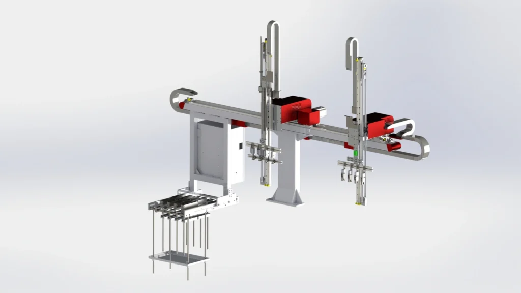
Integrating injection molding robots with branch painting machines starts with a clear match between the two configurations. For PE artificial Christmas tree branches, the robot handles wire insertion and the removal of molded branches. The painting machine receives the branches, positions them, applies color along the central stem and places the finished pieces on a rack.
The available equipment range has three documented robot and painting-machine pairings. Use these pairs as the starting point for a layout review, then check the branch, mold and transfer requirements for the intended installation.
Three matching configurations
| Configuration | Injection molding robot | Branch painting machine |
|---|---|---|
| Single-Level, 2-Output | Single-Level, 2-Output Robot | Single-Level, 2-Output Painting Machine |
| Single-Level, 4-Output | Single-Level, 4-Output Robot | Single-Level, 4-Output Painting Machine |
| Dual-Level, 4-Output | Dual-Level, 4-Output Robot | Dual-Level, 4-Output Painting Machine |
The single-level pairs bring the corresponding robot and painting configurations together. The dual-level pair adds a layout with upper and lower receiving, painting and product-collection areas on the painting machine. Those positions need to be considered alongside the robot’s branch presentation and the space available around the equipment.
Understand what the configuration names describe
Single-Level and Dual-Level describe the equipment arrangement. The 2-Output and 4-Output labels identify the documented output configurations; they do not describe the number of motion axes. They also do not provide a formula for calculating hourly production.
Each product page carries its own specifications and operating conditions. Review those figures for the selected machine and the intended application. A four-output label alone is not evidence that a complete robot-and-painting workstation will produce twice as many finished branches as a two-output installation.
Review the transfer between machines
The connection between the two machines deserves the same attention as either machine individually. The robot needs to handle the specified wire, reach the mold and grip the molded branch. The painting machine needs the branch presented at its receiving position so it can locate the product and follow the required stem-painting path.
Review the mold-hole layout, wire dimensions, gripping areas and placement position together. For the painting stage, identify the branch shape, the central-stem area to be colored and the desired finish. Include the receiving-section layout and access to paint supplies and product racks when discussing the installation.
Prepare a useful application brief
Provide representative branch samples or drawings, the wire specification, mold information and details of the existing injection molding machine. Add the required stem color, paint information, target hourly output and proposed collection arrangement. These inputs allow the robot handling and painting stages to be reviewed as a connected workflow.
The documented pairing identifies the corresponding equipment configurations. The final interface, transfer positions, working sequence and achievable output still need to be agreed for the actual branch and production layout. Start with the matching pair above, then use the individual product details to define that review.